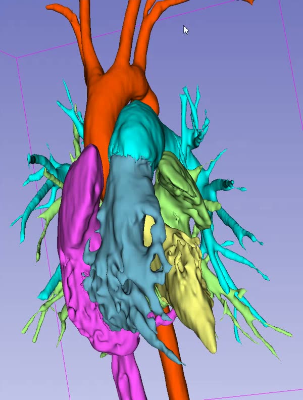
Create a case, segment the heart, explore it in 3D
Short walkthroughs that follow one congenital heart disease case from the casebook, through segmentation in Trinetra Segment, to an interactive model in Trinetra Studio, then on to virtual imaging, virtual surgery, implant planning and a finished report. Each part has a short video, then step-by-step screenshots. Click any screenshot to open it full size.
Casebook→Segment→Studio→Plan→Report
Part 1 · Casebook · ~3 minutes
Creating a case in the Trinetra casebook
Slow stretches such as typing are sped up. A red badge in the corner shows the speed.
Every patient case in Trinetra starts in the casebook. A case holds the case details, its imaging files and its stage in the workflow. Everything stays on this computer ("Local only — nothing leaves this device").
Step 1Create a new case
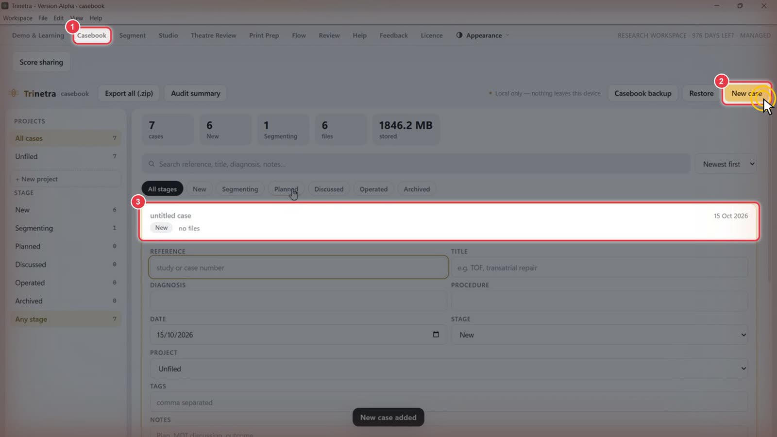
Click Casebook in the top menu.
Click New case, the gold button at the top right.
A blank untitled case appears at the top of the list, and a New case added message confirms it.
Step 2Fill in the case details
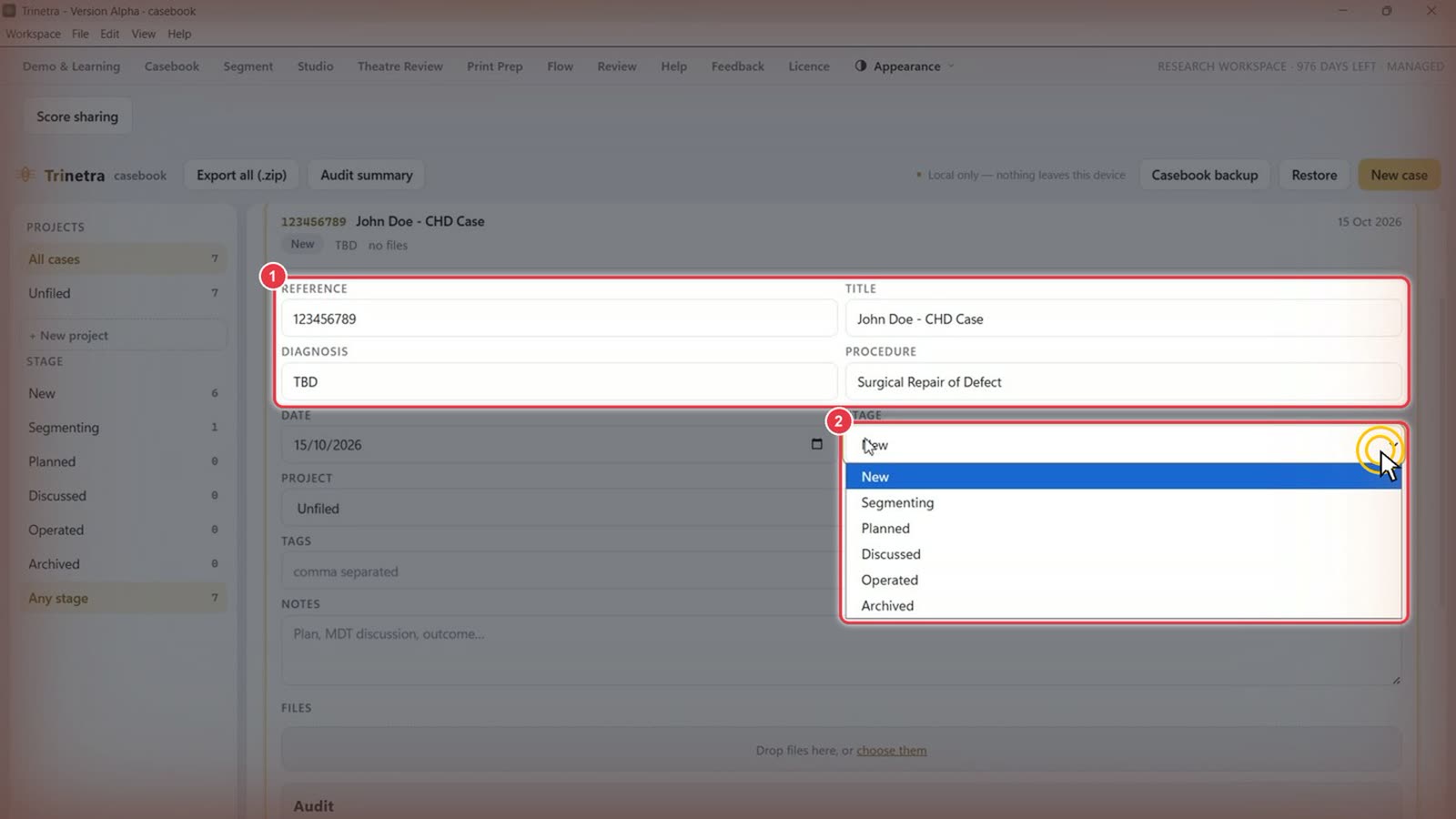
Fill in the case details:
Field
What to enter
Reference
Any identifier you use: MRN, hospital number, study ID, etc.
Title
A short, recognisable name, e.g. "John Doe – CHD Case"
Diagnosis
The working diagnosis. "TBD" is fine for now
Procedure
The planned procedure, e.g. "Surgical Repair of Defect"
Date
Defaults to today
Click the Stage dropdown to set where the case is in the workflow: New → Segmenting → Planned → Discussed → Operated → Archived. New cases start at New. Stages are for your own tracking. Move a case along as it progresses, and use the Stage filters in the sidebar to see what's at each point.
Step 3Create a project
Projects group related cases, for example by hospital, study or surgeon.
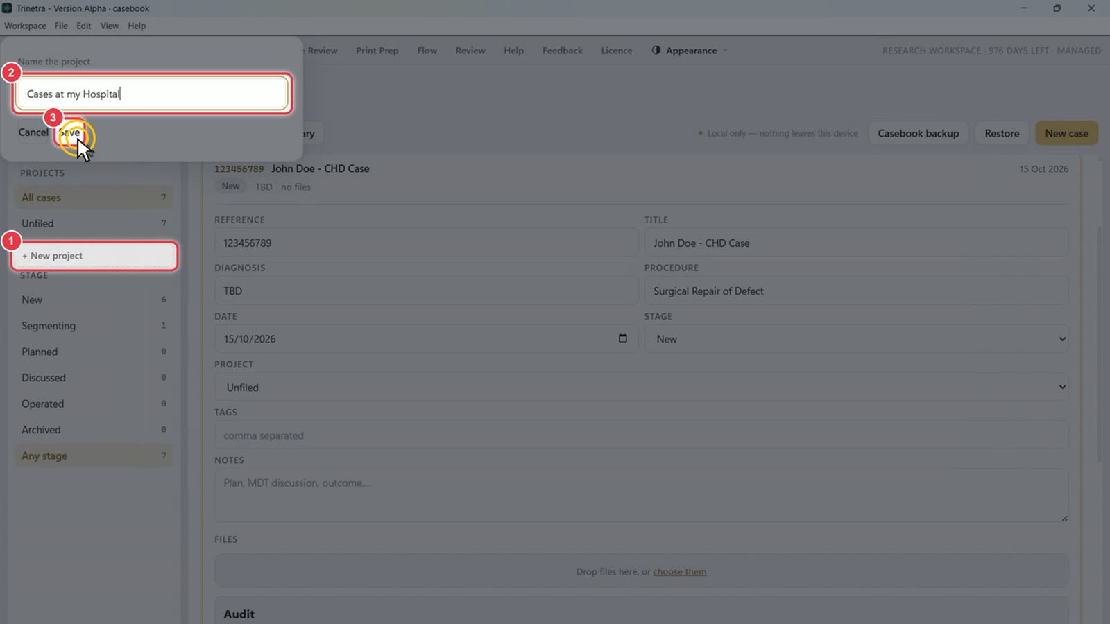
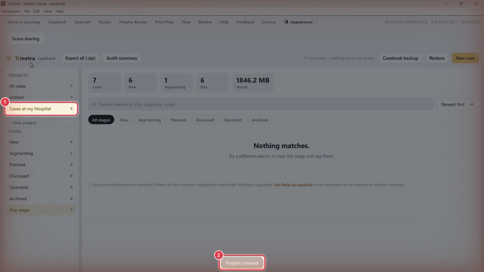
Click + New project in the left sidebar.
Type a name, e.g. "Cases at my Hospital".
Click Save.
The new project appears under Projects.
A Project created message confirms it.
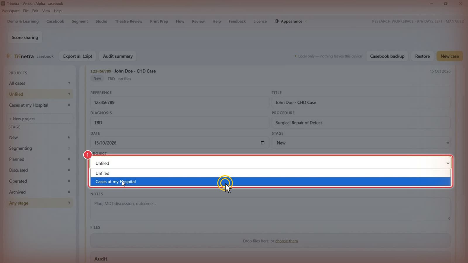
Step 4Put the case in the project
Go back to your case. Open the Project dropdown and choose your project instead of Unfiled.
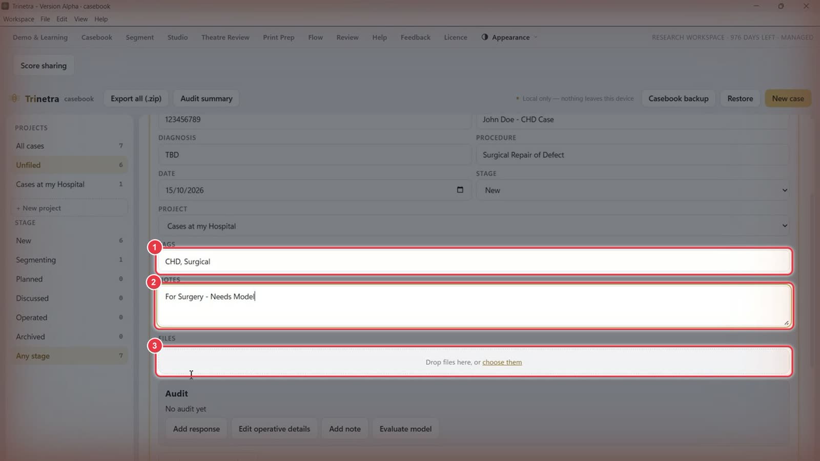
Step 5Add tags, notes and files
Tags: comma-separated keywords, e.g. CHD, Surgical. Tags become filter chips at the top of the casebook.
Notes: the plan, MDT discussion or outcome, e.g. "For Surgery – Needs Model".
Files: drag and drop reports, letters and other documents onto the box so they're kept with the case. You can also click choose them to browse. Dragging and dropping is quickest.
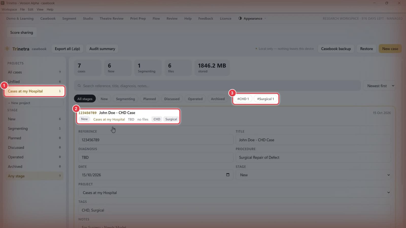
Step 6Check the case
Click your project in the sidebar to see only its cases.
The case header shows the reference, title, stage, project and tags.
New tags appear as filter chips (#CHD, #Surgical). Click one to filter the list.
Step 7Open the case for segmentation
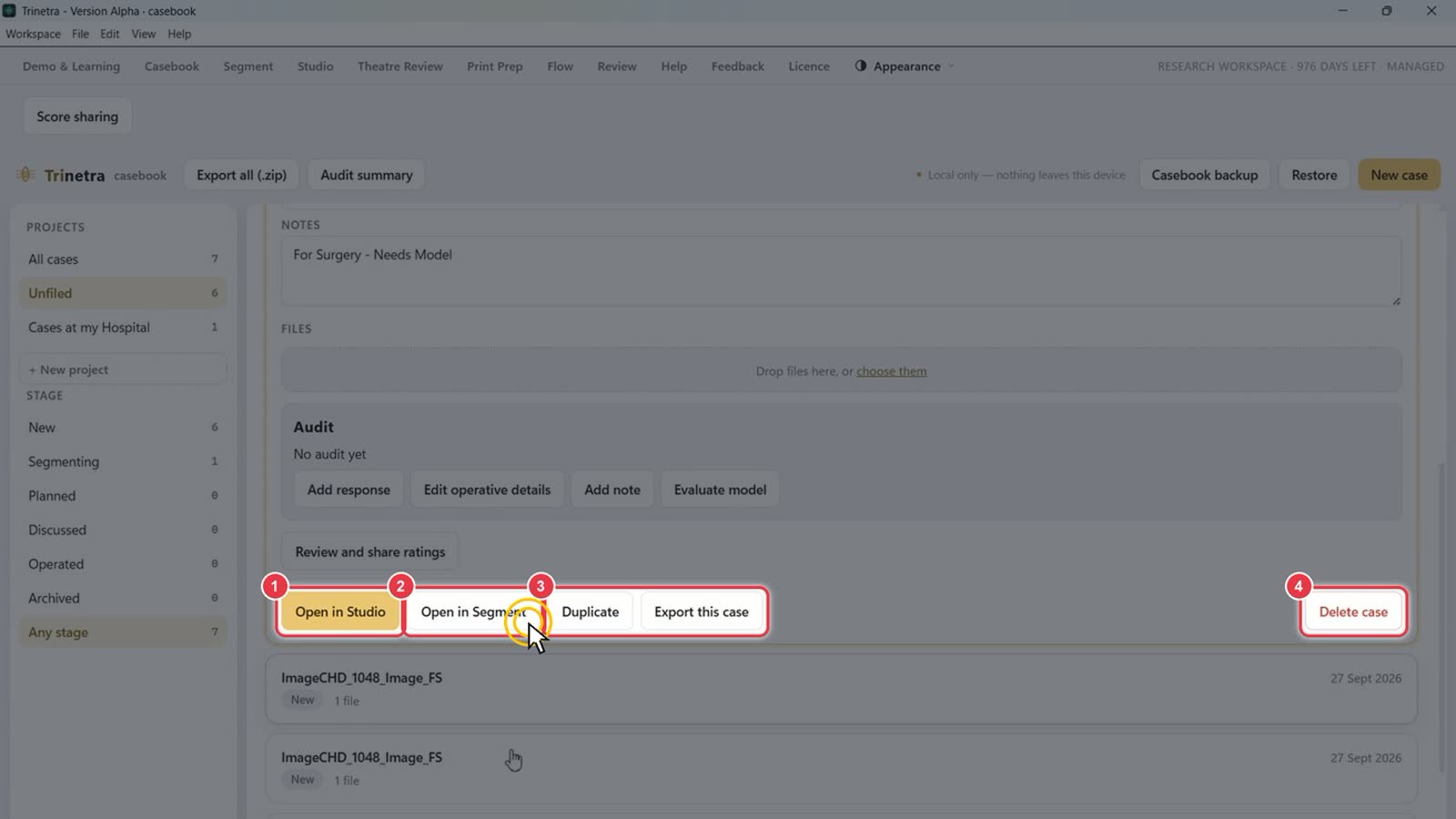
Scroll to the bottom of the case for its actions:
Open in Studio: view the case's 3D model.
Open in Segment: segment the scan in Trinetra Segment. Click this now.
Duplicate / Export this case.
Delete case.
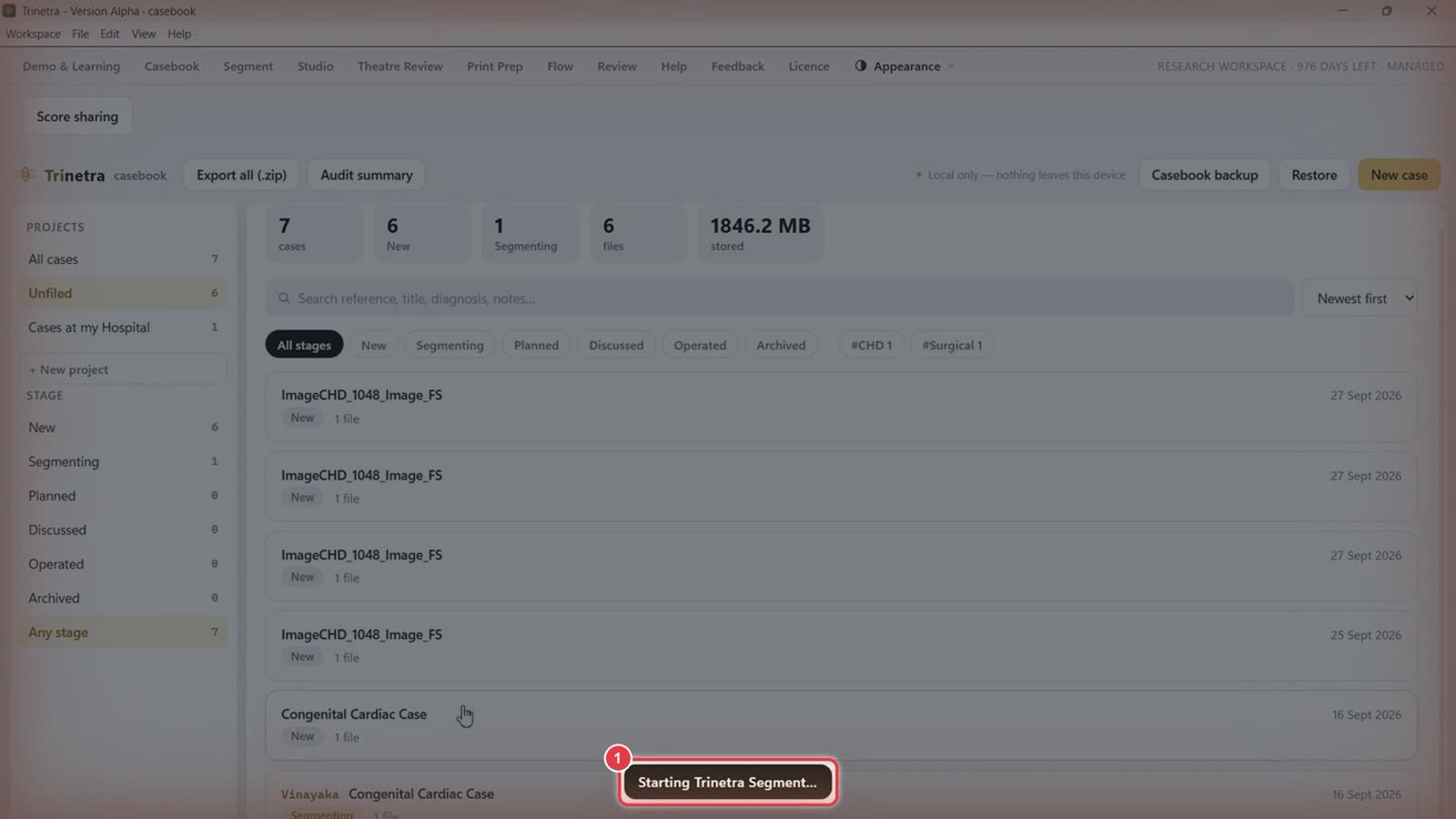
Trinetra shows Starting Trinetra Segment… while it launches. This can take up to a minute.
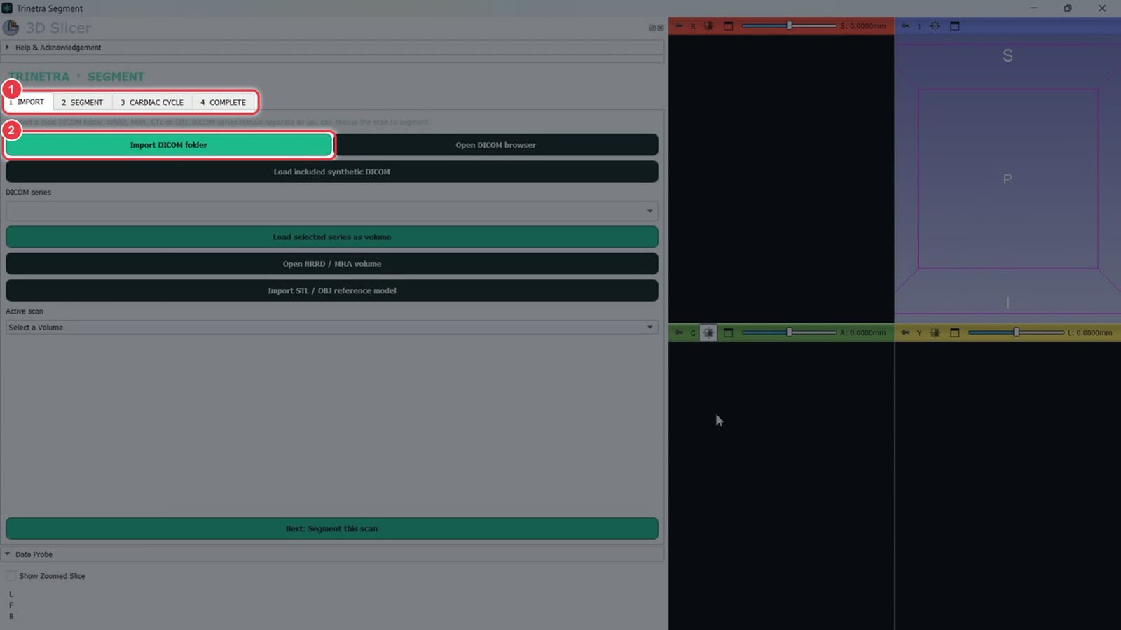
Trinetra Segment opens in its own window, running on 3D Slicer.
The four tabs show the workflow: 1 Import → 2 Segment → 3 Cardiac Cycle → 4 Complete.
You start on Import. Continue with Part 2 — Segmenting a cardiac case.
Part 2 · Trinetra Segment · ~10 minutes
Segmenting a cardiac case in Trinetra Segment
Slow stretches such as typing are sped up. A red badge in the corner shows the speed.
Trinetra Segment runs inside 3D Slicer and opens from the casebook (Open in Segment, see Part 1). Work left to right through the tabs: 1 Import → 2 Segment → 3 Cardiac Cycle → 4 Complete. The 3D model updates live in the right-hand panel.
Step 1Import the scan
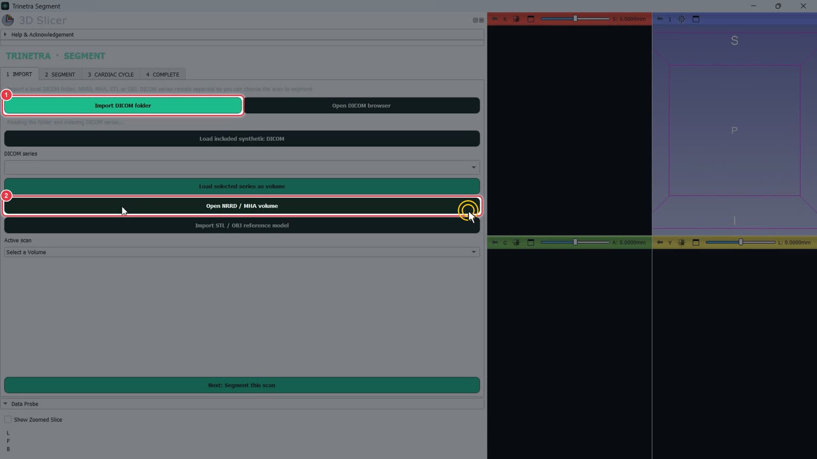
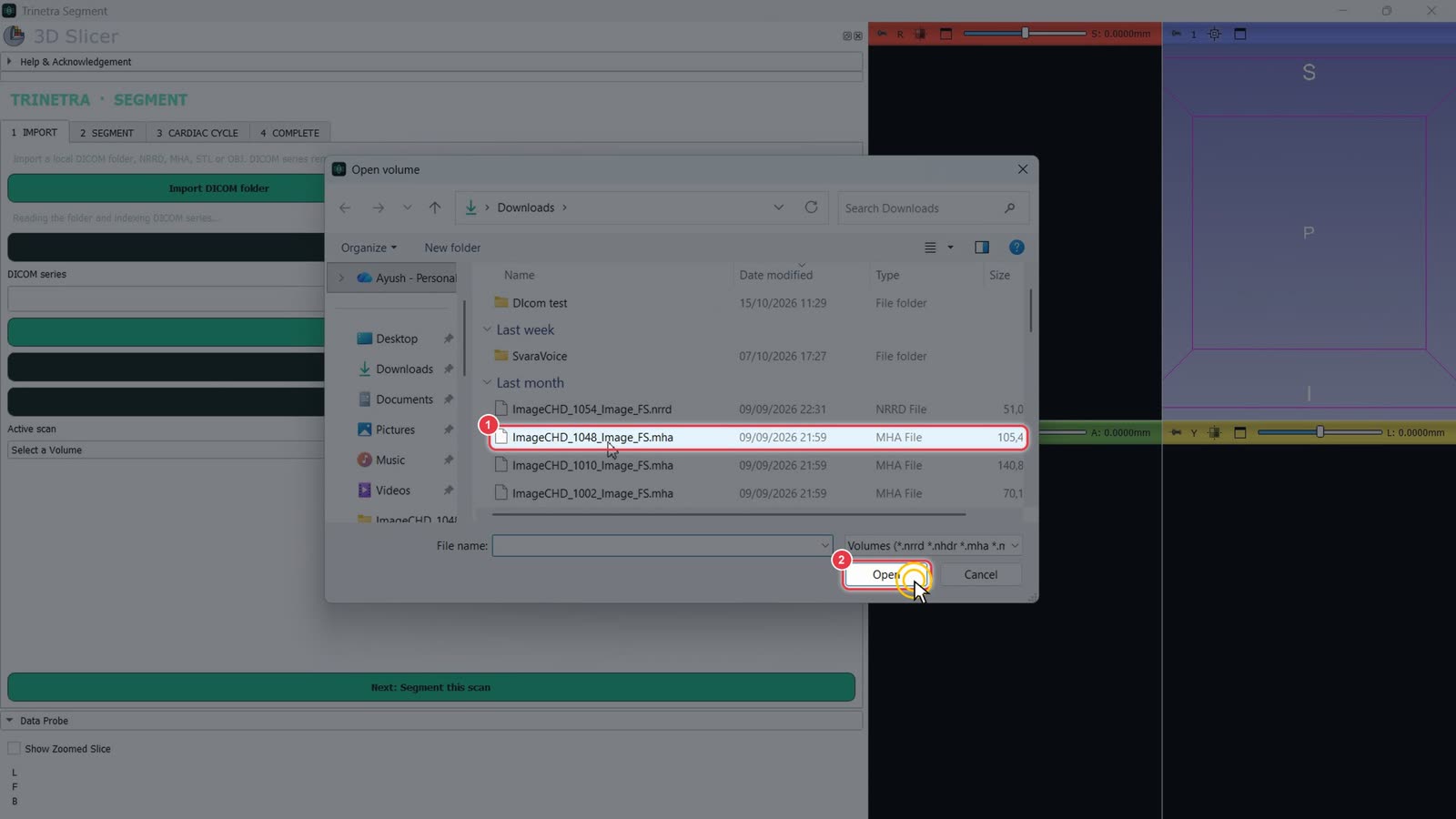
On the 1 Import tab, pick how to load the scan:
Import DICOM folder: for a folder of DICOM files straight from PACS.
Open NRRD / MHA volume: for a single volume file. This example uses one.
Select the scan file.
Click Open.
Step 2Check the scan and move to Segment
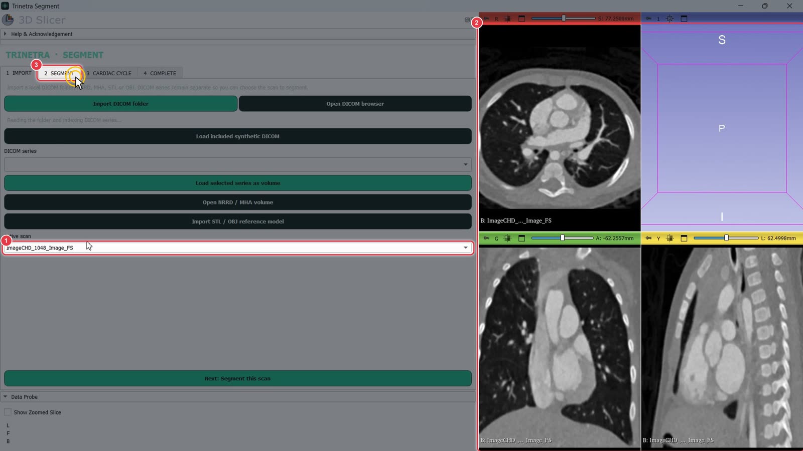
Active scan now shows the loaded scan.
The axial, coronal and sagittal views show the CT.
Click the 2 Segment tab.
Step 3Threshold the blood pool
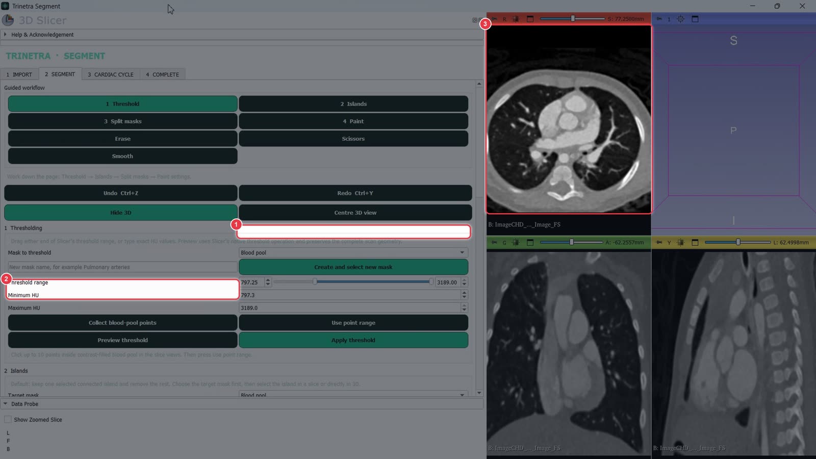
The Guided workflow buttons at the top follow the order of the page: Threshold → Islands → Split masks → Paint.
Drag the left end of Threshold range until the contrast-filled blood pool is covered. You can also type the values into Minimum HU and Maximum HU.
Preview threshold shows the result without saving it.
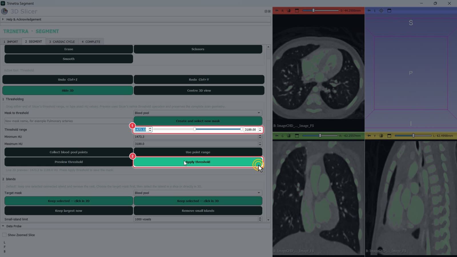
The green overlay shows what's included. Aim to fill the chambers and vessels without leaking into the surrounding tissue.
When the range looks right (about 1470 HU and up in this example),
click Apply threshold.
Step 4Separate the bones
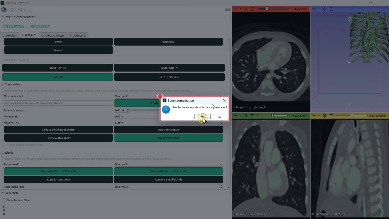
Trinetra asks "Are the bones important for this segmentation?"
Yes: opens the Bone separation panel. Bone is split off into its own Chest wall mask, so you can show it alongside the heart. This example uses Yes.
No: skips the panel and goes straight to the Islands tool. Click the heart and Trinetra keeps it, plus anything connected to it, and removes the rest.
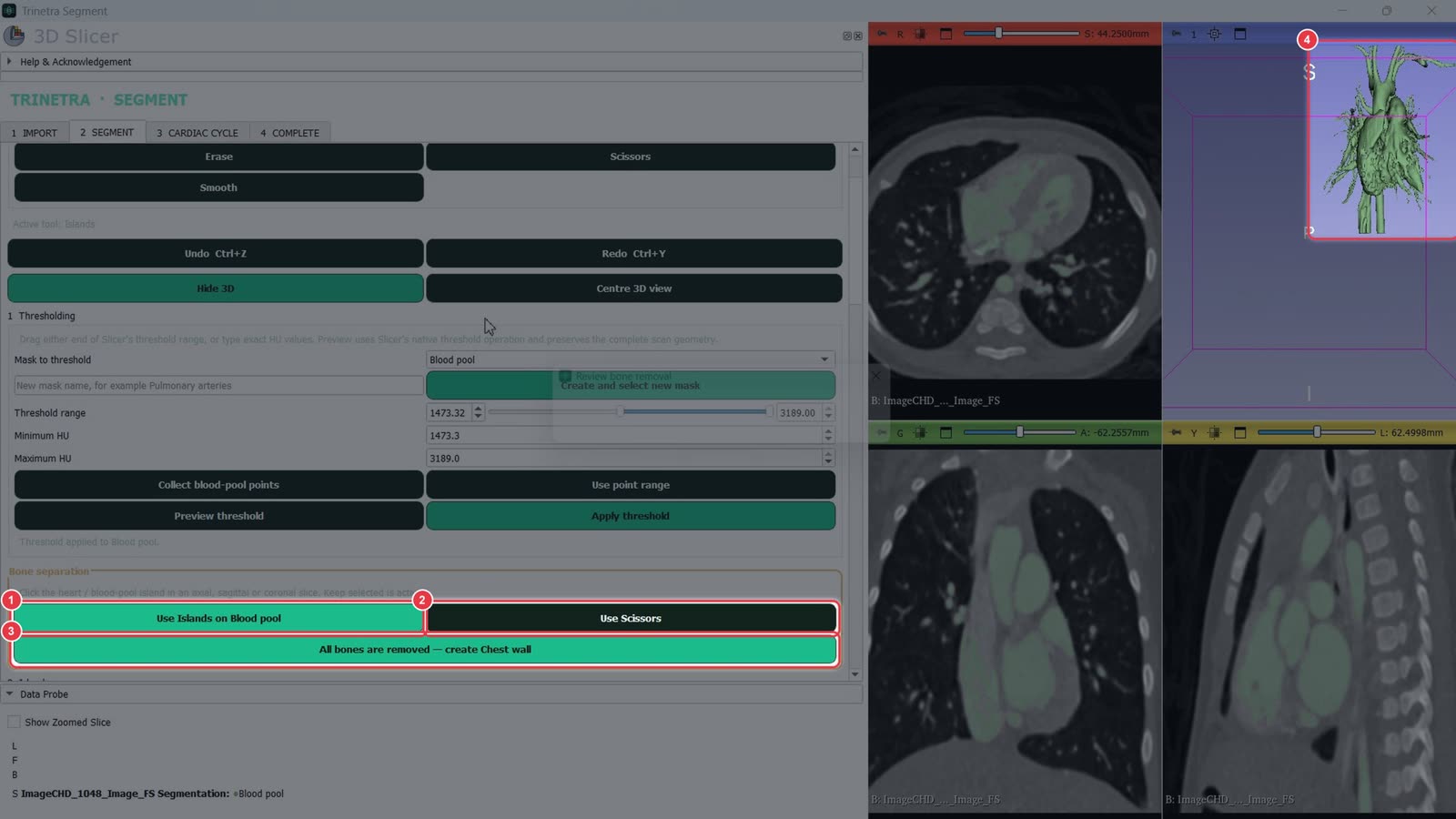
In the Bone separation panel, separate bone from the blood pool. Bone that touches the heart may still be attached:
Use Islands on Blood pool: click the heart in a slice view to keep it and drop disconnected bone.
Use Scissors: cut away bone that's still attached (next step).
All bones are removed — create Chest wall: click once the heart is clean. The removed bone is kept as a separate Chest wall mask.
Check the 3D view as you go.
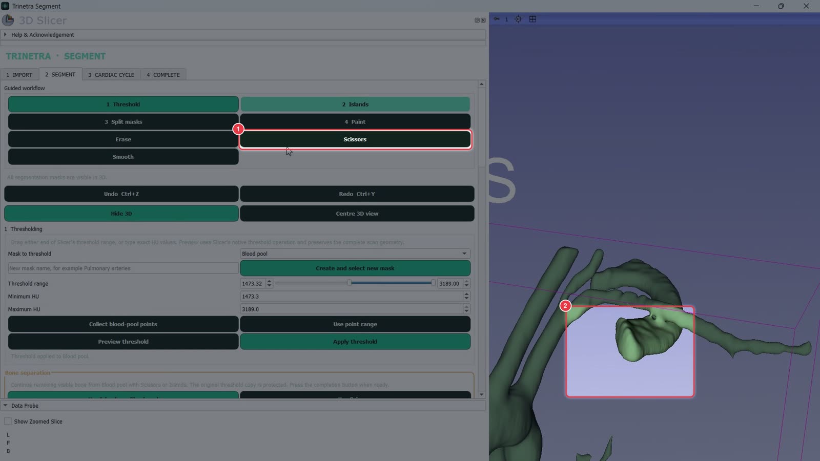
With Scissors active,
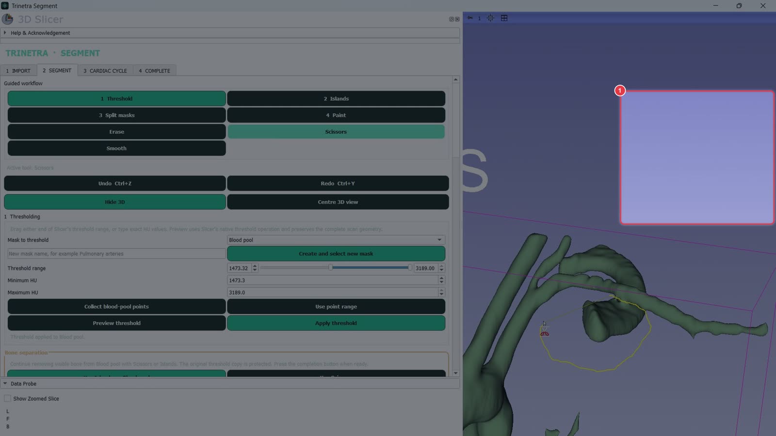
draw a loop around the unwanted part in the 3D view to cut it away. Rotate the model and repeat as needed. Undo is Ctrl+Z.
The blood pool now shows only the heart and great vessels.
Step 5Name the splitting masks
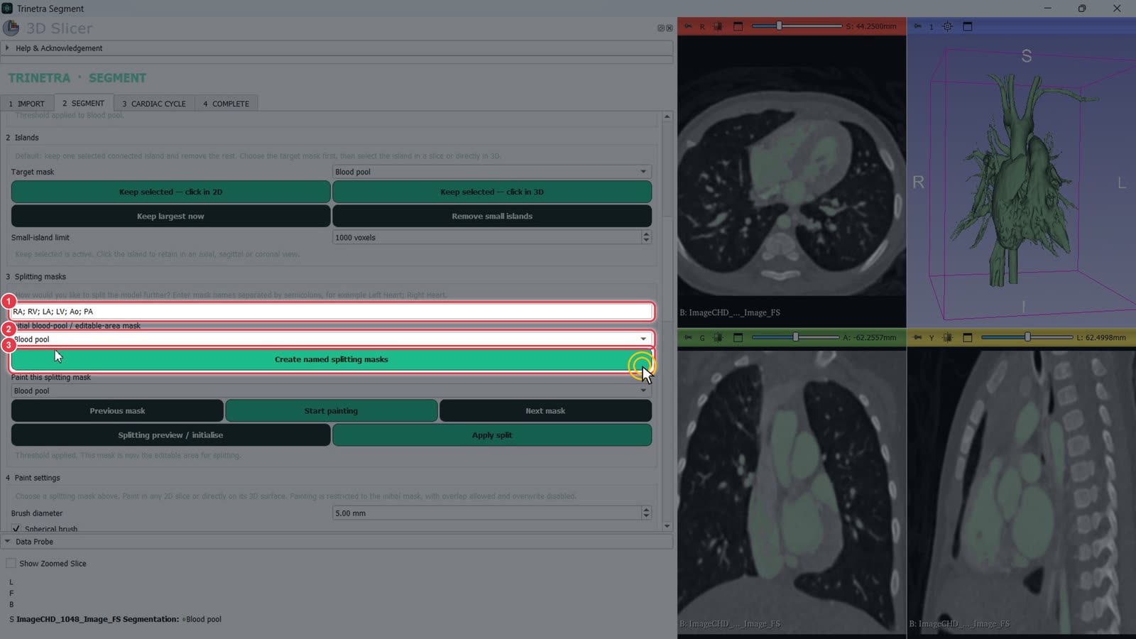
Type the structures you want, separated by semicolons. For example: RA; RV; LA; LV; Ao; PA.
Leave Initial blood-pool / editable-area mask set to Blood pool.
Click Create named splitting masks.
Step 6Paint a seed on each structure
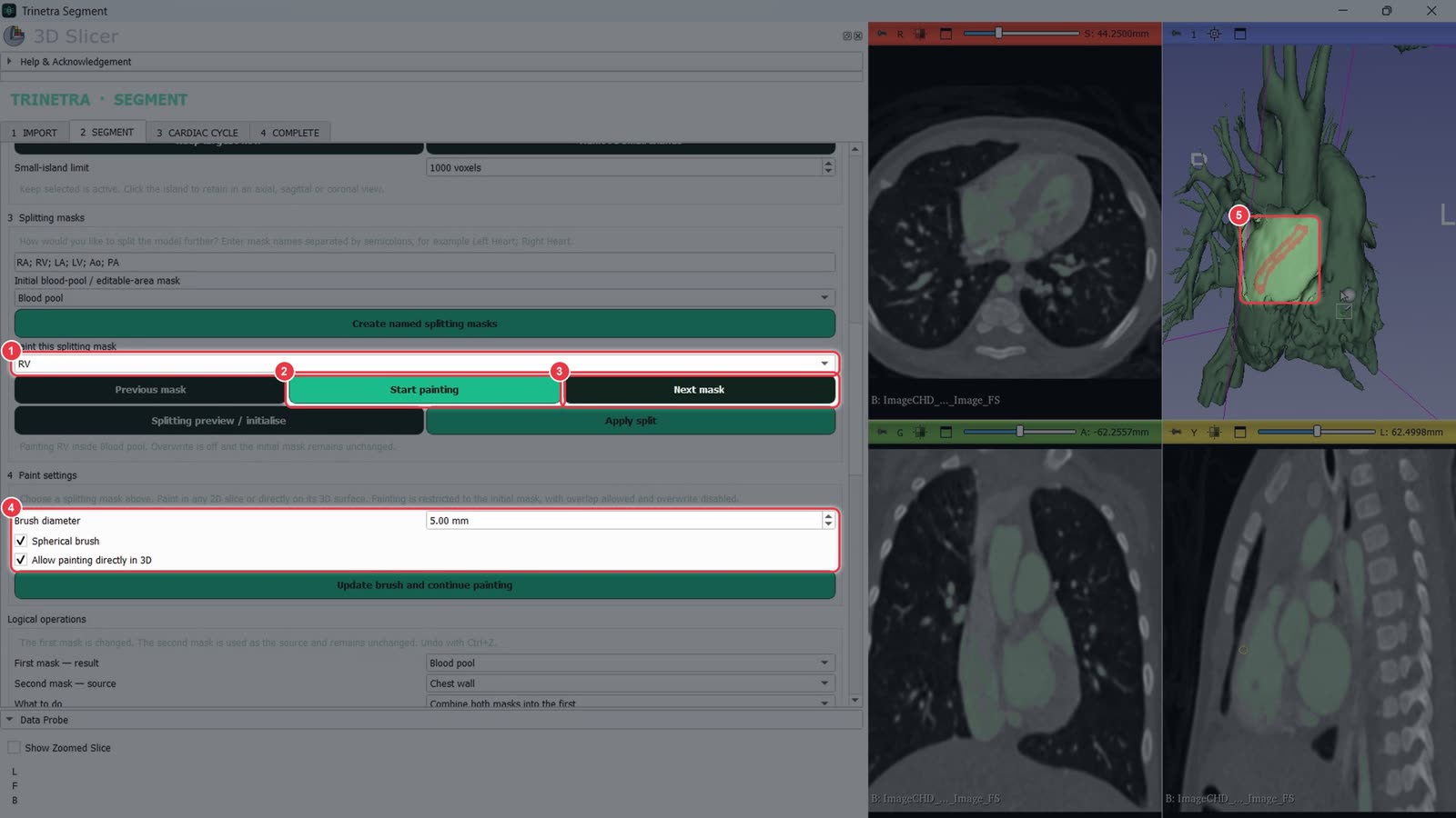
Choose a mask in Paint this splitting mask, e.g. RV.
Click Start painting, then paint a short stroke inside that chamber. You can paint in a 2D slice or directly on the 3D surface.
Click Next mask and repeat for each structure.
Paint settings: brush diameter, spherical brush, and whether painting directly in 3D is allowed.
Your stroke shows on the model in the mask's colour.
Step 7Apply the split
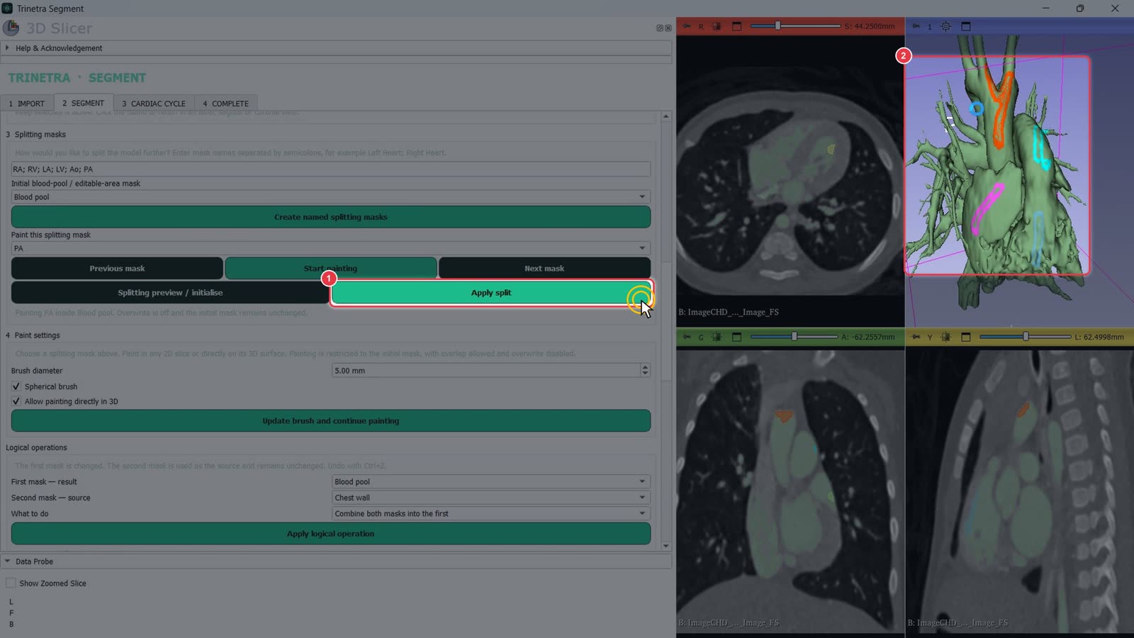
Once every mask has a stroke, click Apply split.
Trinetra grows each stroke to fill its whole structure.
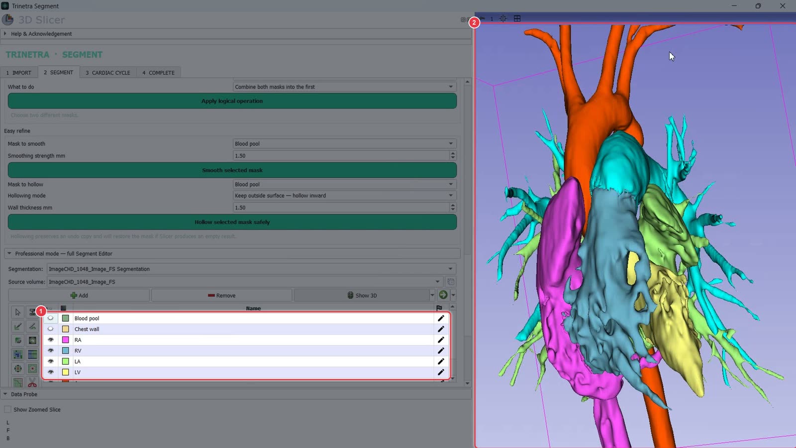
Each structure is now its own coloured segment (RA, RV, LA, LV, Ao, PA).
Rotate the 3D view to check the boundaries. If a region went to the wrong structure, paint more on the correct mask and click Apply split again.
Step 8Complete and send to Studio
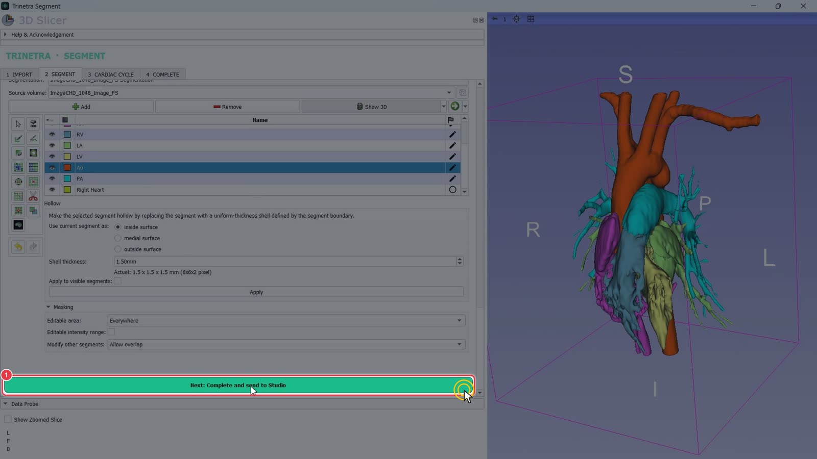
Scroll to the bottom of the Segment tab and click Next: Complete and send to Studio.
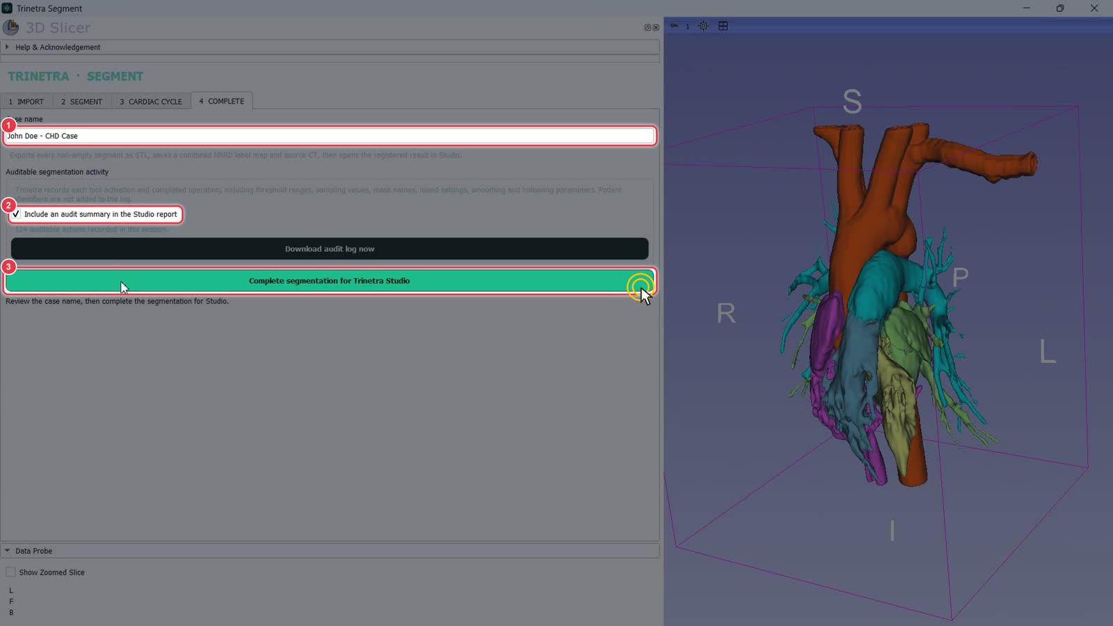
Check the Case name. It's filled in from the casebook.
Leave Include an audit summary in the Studio report ticked to keep a record of the segmentation steps. Patient identifiers aren't logged.
Click Complete segmentation for Trinetra Studio.
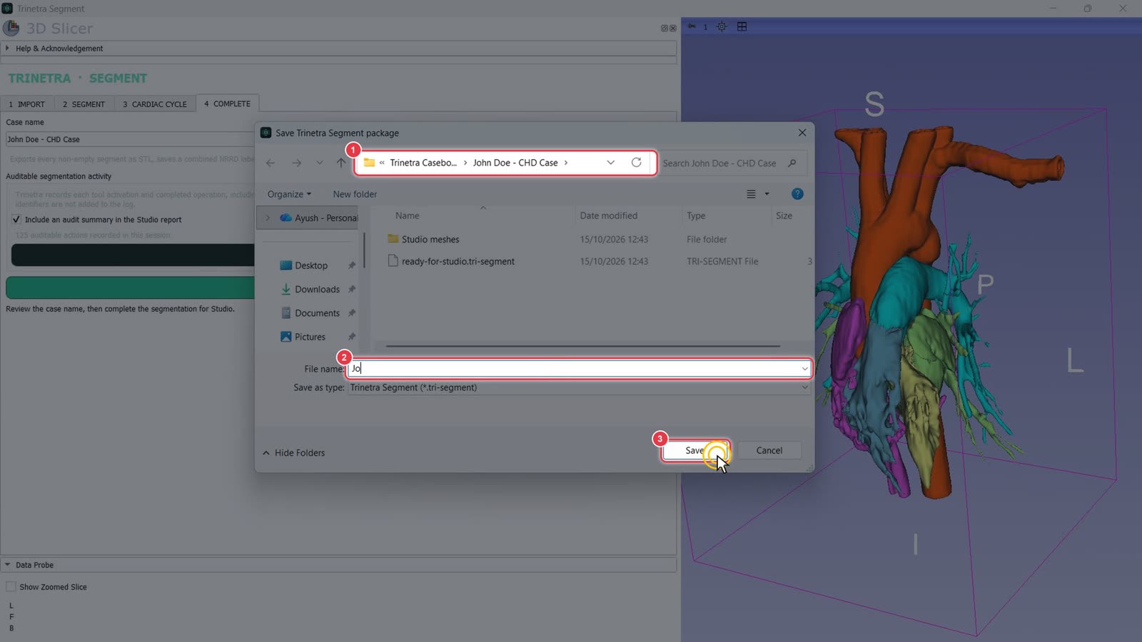
The save dialog opens in the case's own casebook folder.
Name the file.
Click Save.
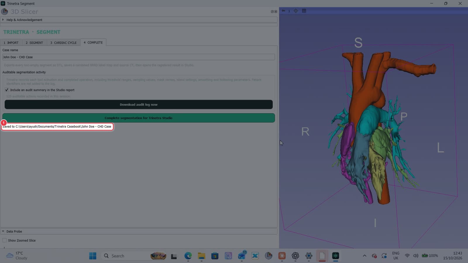
Trinetra confirms where the case was saved. It exports each segment as an STL, plus a label map and the source CT, then opens the result in Trinetra Studio. Continue with Part 3 — Visualising in Trinetra Studio.
Part 3 · Trinetra Studio · ~5 minutes
Viewing and manipulating the model in Trinetra Studio
Slow stretches such as typing are sped up. A red badge in the corner shows the speed.
When you click Complete segmentation for Trinetra Studio (end of Part 2), the case opens in Trinetra Studio with every structure loaded as its own 3D model.
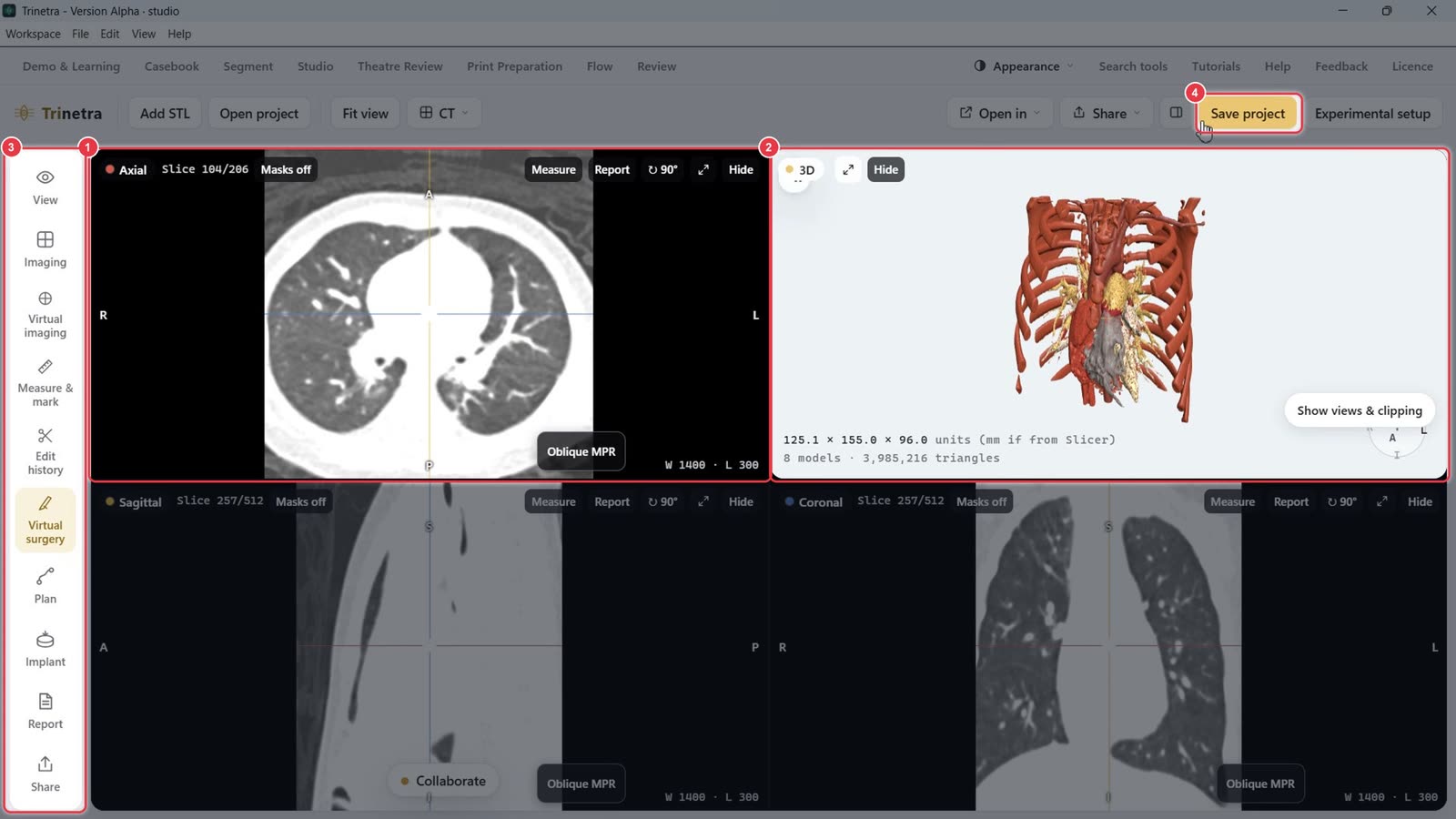
Step 1The Studio screen
CT slice views: axial, sagittal and coronal.
The 3D model.
The tool bar: View, Imaging, Virtual imaging, Measure & mark, Edit history, Virtual surgery, Plan, Implant, Report, Share.
Save project saves everything you change in this part.
Step 2Switch to a 3D-only layout
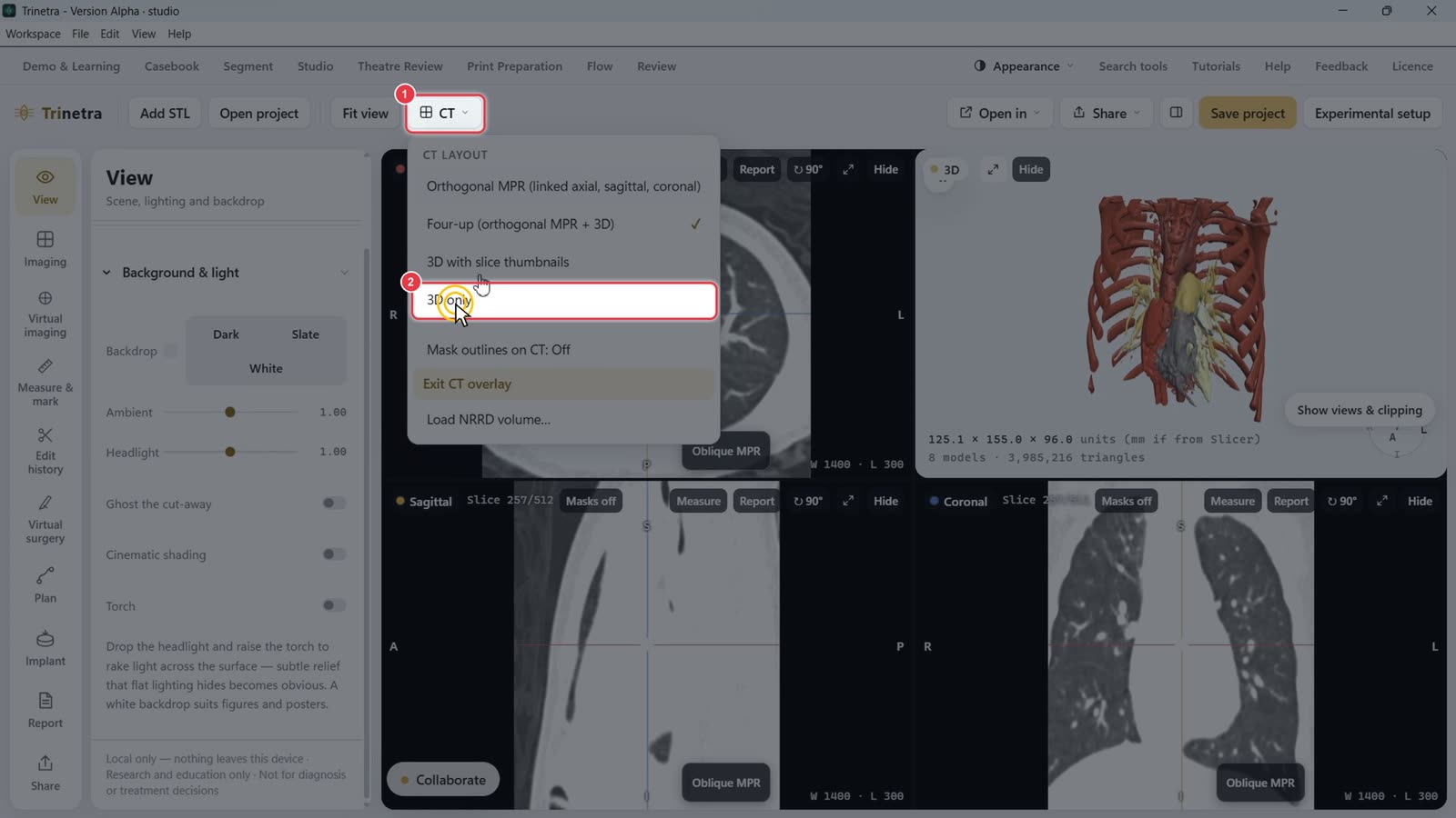
Click the CT menu in the toolbar.
Choose 3D only to give the model the whole screen. Choose Four-up to bring the CT views back.
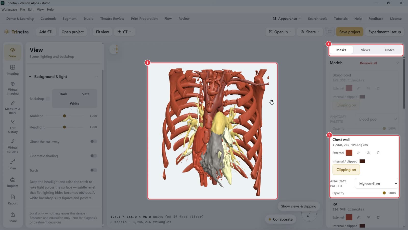
The Masks tab on the right lists every structure (Blood pool, Chest wall, RA, RV, LA, LV, Ao, PA).
Each structure has its own card: colours, show/hide (eye icon), delete, clipping, anatomy palette and opacity.
The model fills the view.
Step 3Fade the chest wall
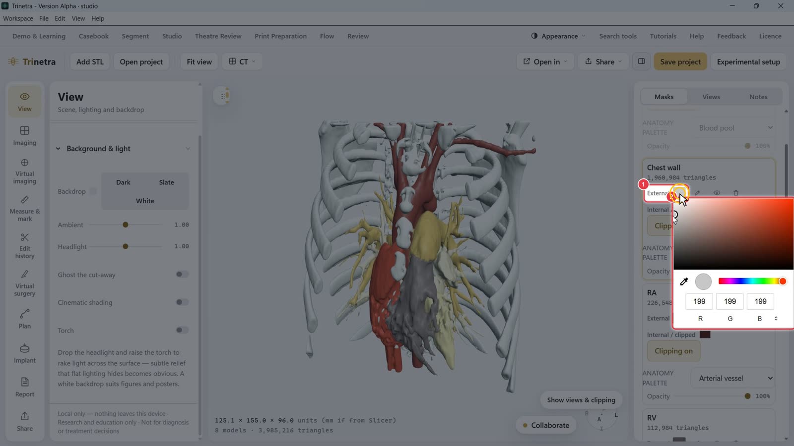
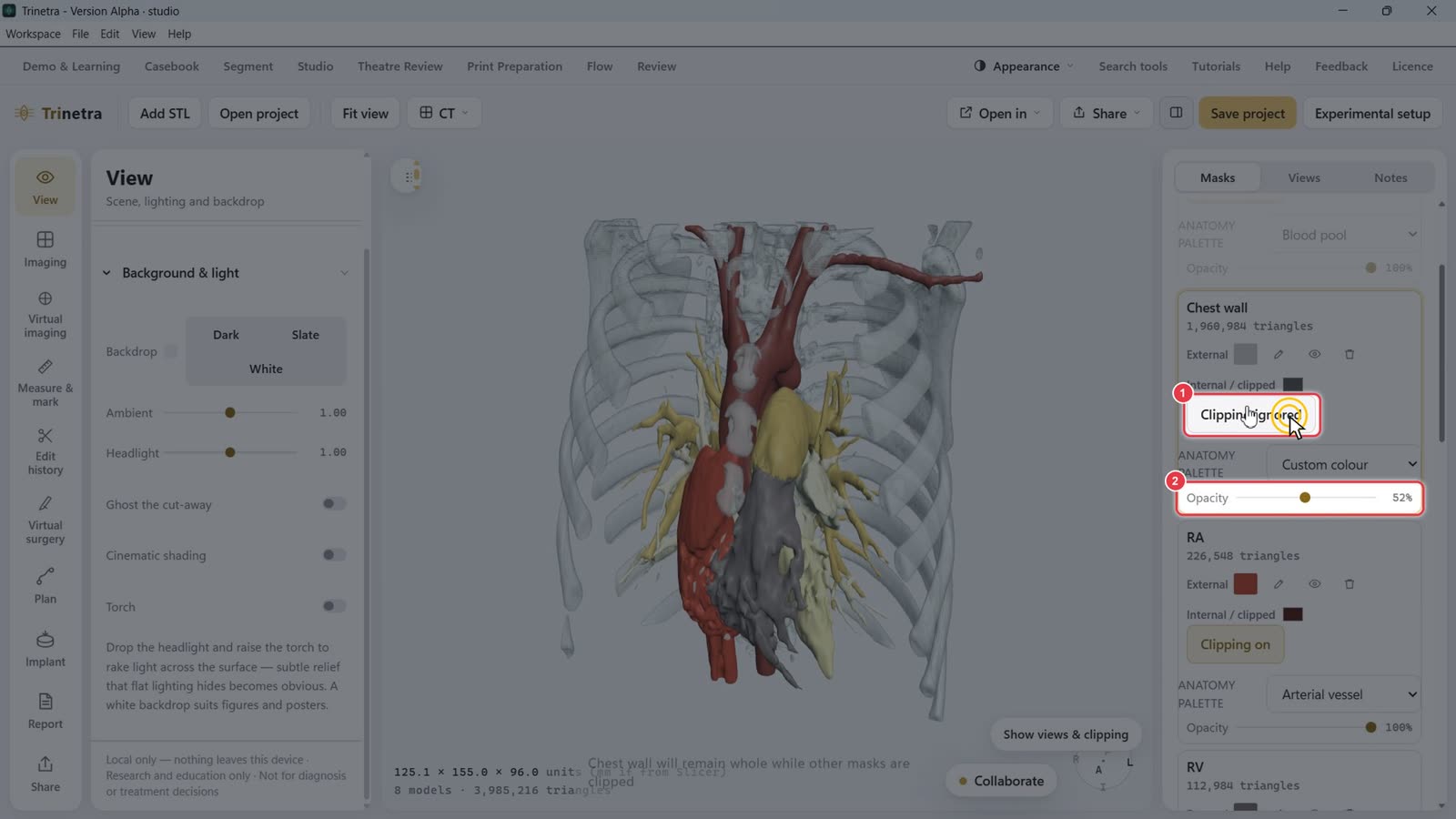
On the Chest wall card, click the External colour swatch.
Pick a colour. A neutral grey works well for bone.
Click Clipping on so it changes to Clipping ignored. The chest wall then stays whole when you cut into the heart later.
Drag Opacity down (about 50%) so you can see through the ribs.
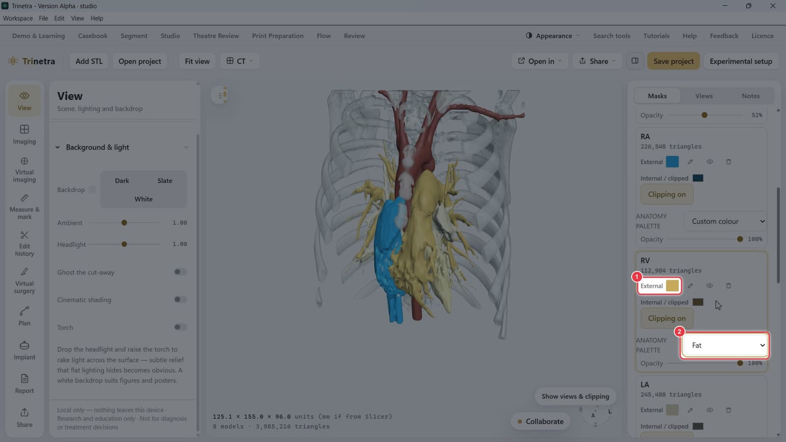
Step 4Colour each structure
For each structure (RA, RV, LA, LV, Ao, PA):
Click the External swatch to pick any colour, or
choose a preset from Anatomy palette (Blood pool, Myocardium, Arterial vessel, Venous vessel, Valve / fibrous tissue, Fat, and others).
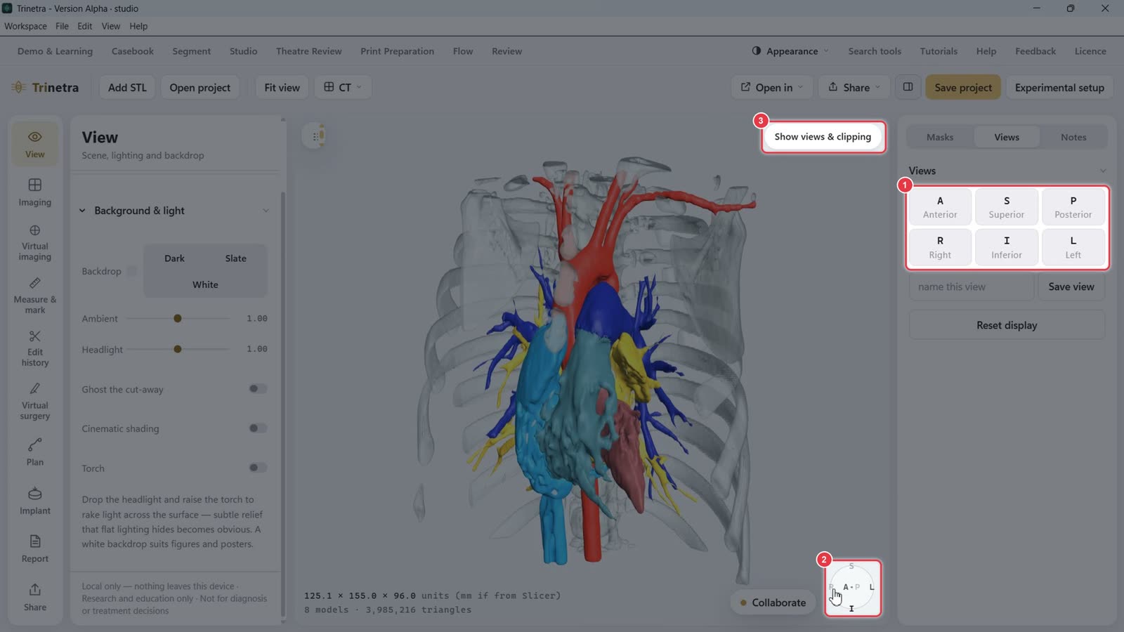
Step 5Jump to standard views
On the Views tab, click A / P / S / I / R / L to snap to anterior, posterior, superior, inferior, right or left.
The orientation cube in the bottom corner always shows which way you're facing.
Show views & clipping opens the floating Saved Views and Clipping panel.
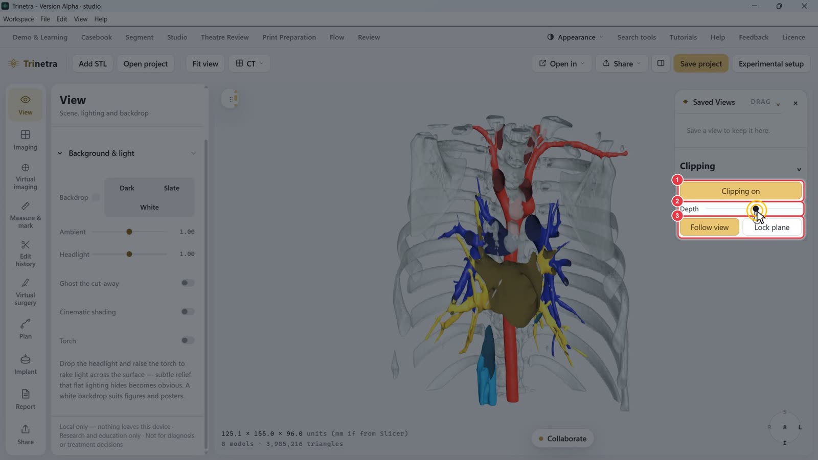
Step 6Clip into the heart
Click Clipping off to turn it to Clipping on. A cutting plane slices through the model.
Drag Depth to move the plane deeper or shallower.
Follow view: the plane stays facing you as you rotate. Lock plane: it stays fixed so you can rotate around the cut.
Because the chest wall is set to Clipping ignored, the ribs stay whole while the chambers are opened up.
Step 7Save named views
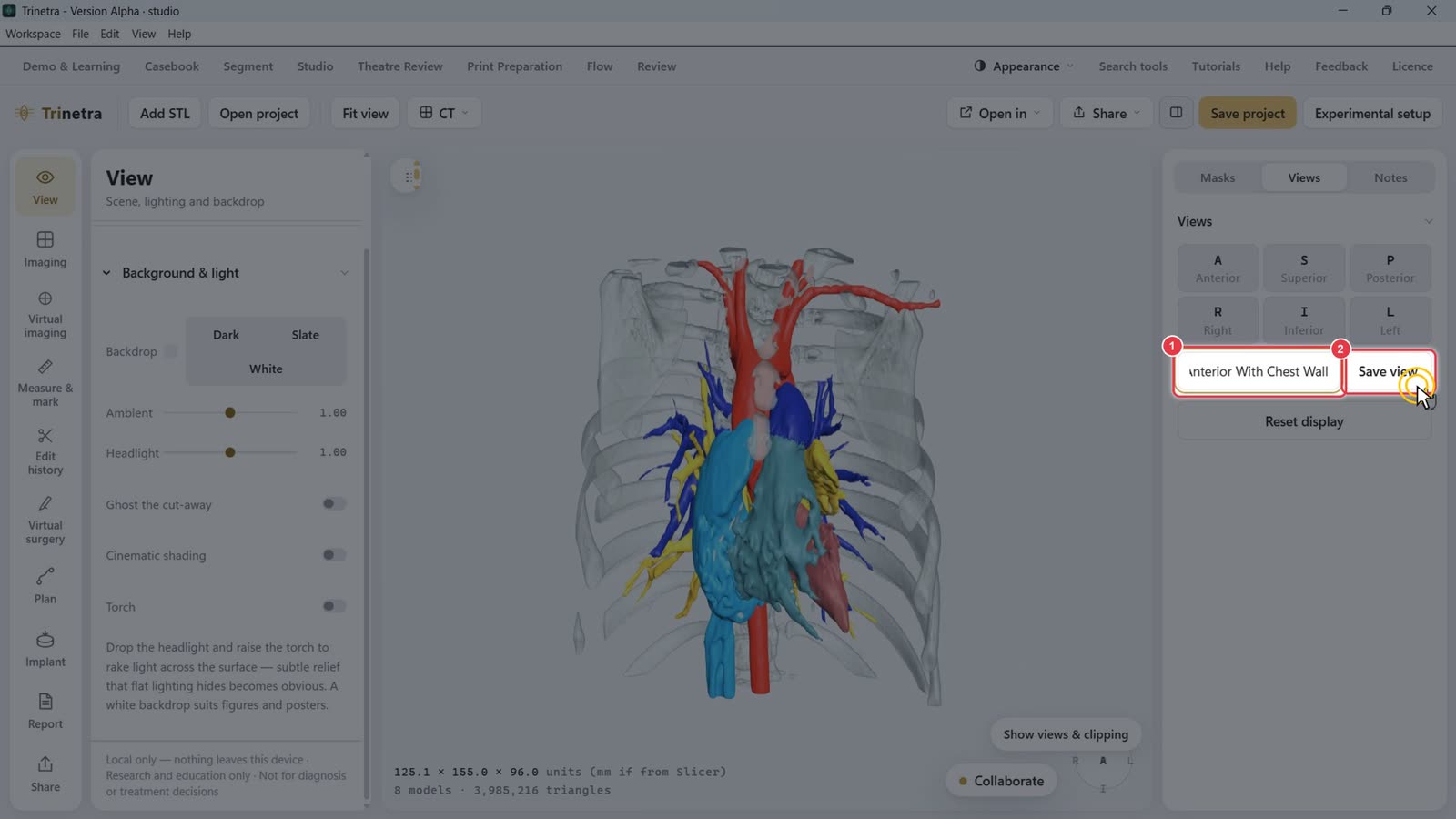
Set up the angle you want, then type a name, e.g. "Anterior With Chest Wall".
Click Save view.
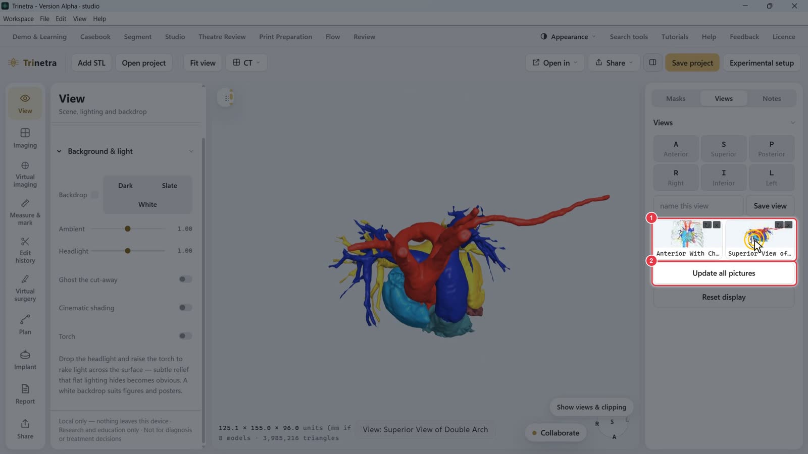
Each saved view keeps the camera, clipping and visibility, with a thumbnail. Click one to jump back to it.
Update all pictures refreshes the thumbnails.
Step 8Add notes
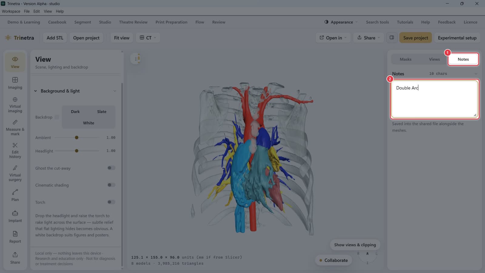
Open the Notes tab.
Type case notes, e.g. "Double Arch". Notes are saved in the shared file alongside the meshes.
Step 9Lighting and effects
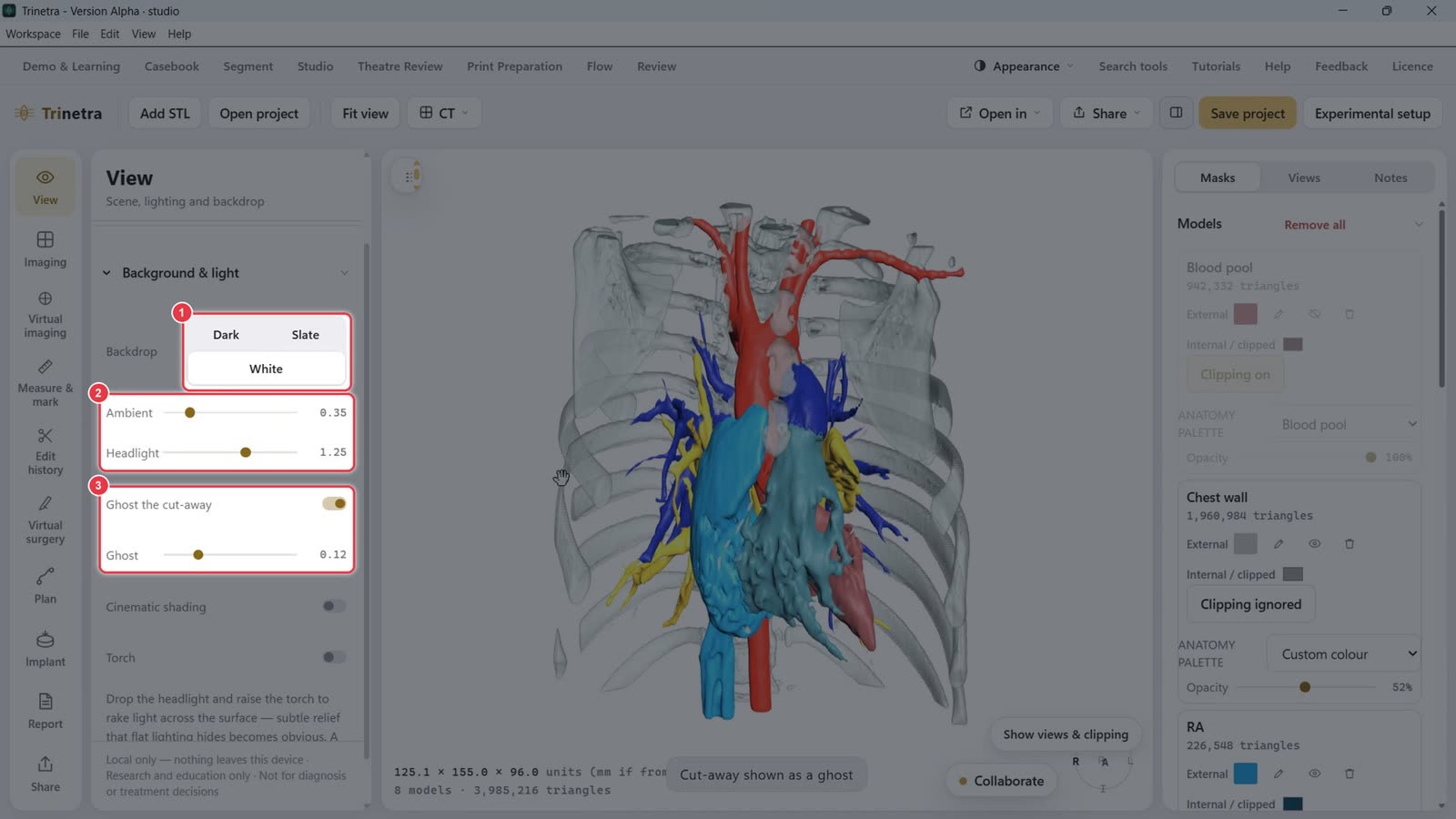
On the left View panel, under Background & light:
Backdrop: Dark, Slate or White. White suits figures and posters.
Ambient and Headlight set overall brightness and the light from the camera.
Ghost the cut-away: shows clipped-away parts as a faint ghost. Ghost sets how faint.
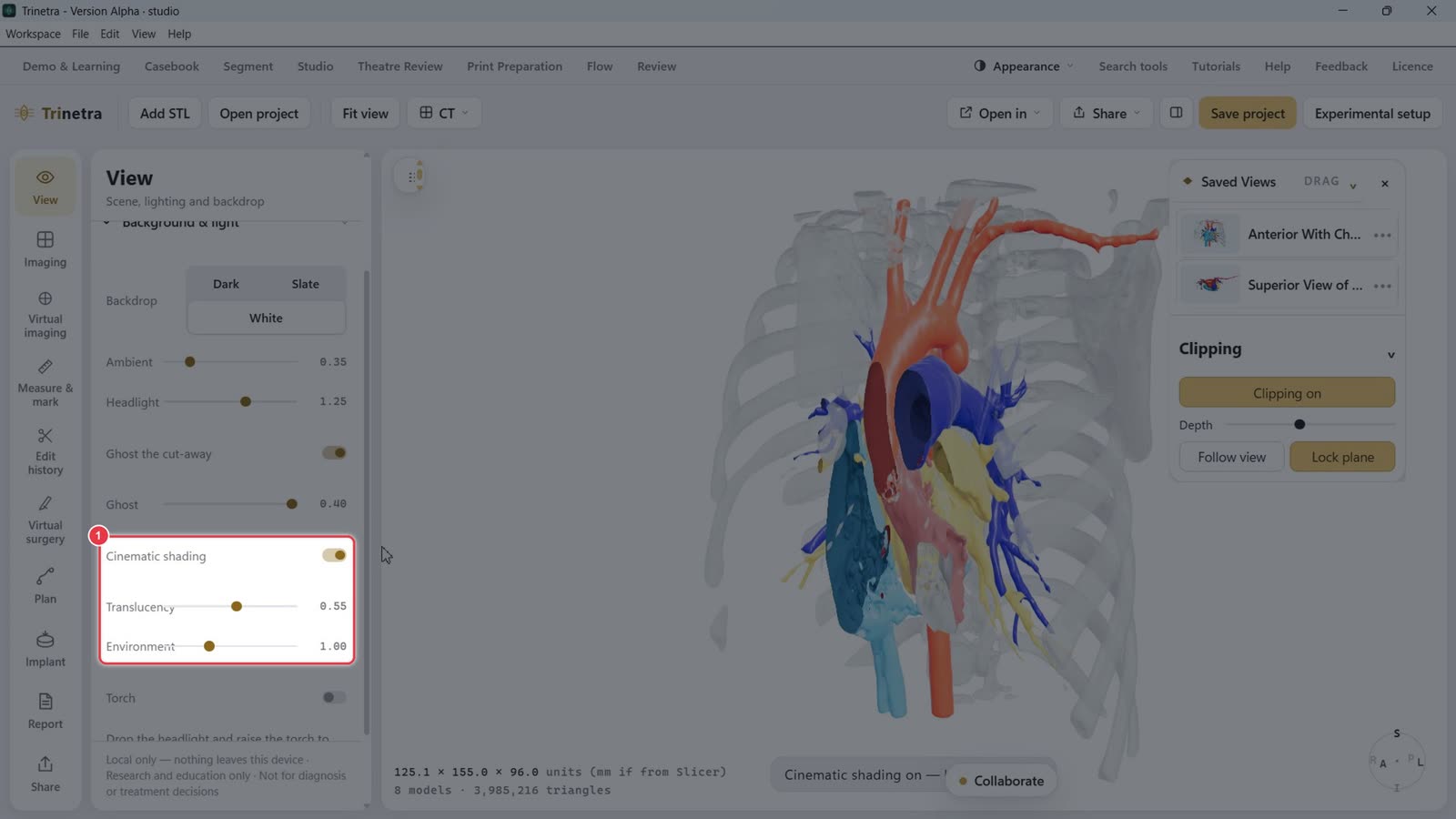
Cinematic shading gives more realistic lighting, with Translucency and Environment sliders.
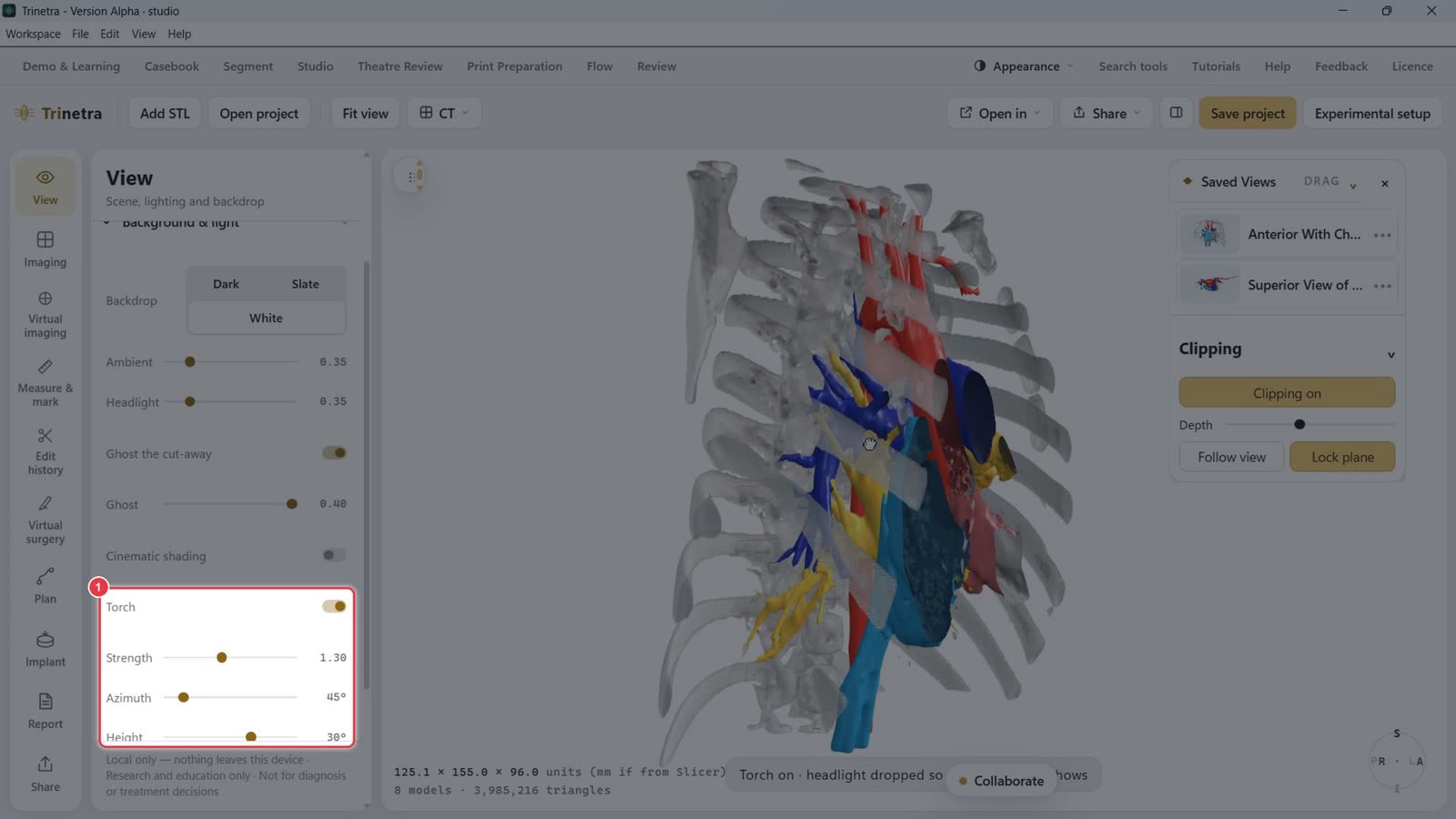
Torch adds a side light (Strength, Azimuth, Height). Lower the headlight and raise the torch to bring out surface detail.
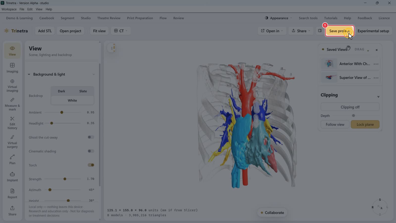
Step 10Save the project
Click Save project to keep colours, views, clipping and notes with the case.
Part 4 · Advanced tools · ~12 minutes
Virtual imaging, virtual surgery and implants
Slow stretches such as typing are sped up. A red badge in the corner shows the speed.
These tools live in the left tool bar of Trinetra Studio. The flyout next to the 3D view gives one-click access to the same tools (Endoscope, Measure, Annulus, Scissor, Sculpt, Surface path, Route) plus Undo last edit.
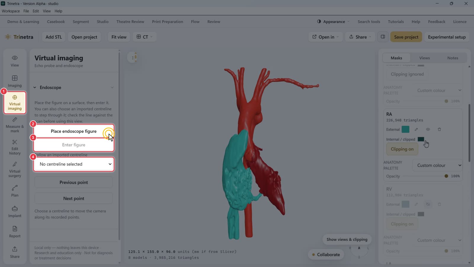
Step 1Fly through with the virtual endoscope
Click Virtual imaging in the left tool bar.
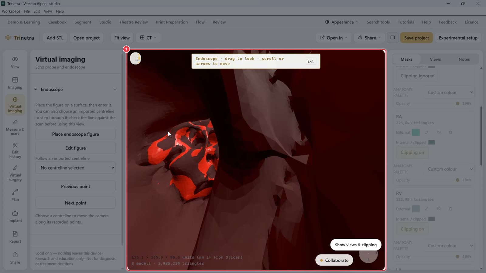
Click Place endoscope figure, then click a point on the model's surface. Hide any structures in the way first, using the eye icon on their mask card.
Click Enter figure to look out from that point.
To follow a vessel, choose an imported centreline and step along it with Previous point / Next point.
You're now inside the anatomy. Drag to look around, and scroll or use the arrow keys to move forward and back. Click Exit (top of the view) or Exit figure to leave.
Step 2Simulate an echo with the echo probe
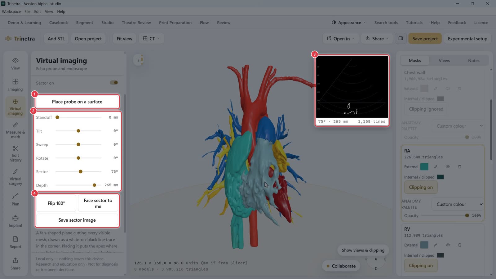
Open Echo probe, then click Place probe on a surface and click where the probe should sit.
Adjust the beam:
Standoff: lifts the probe off the surface, for the gap between chest wall and heart.
Tilt, Sweep and Rotate: aim the fan.
Sector: widens or narrows the fan.
Depth: how far the beam reaches.
The inset shows the simulated echo cut: every visible mesh as a white-on-black line trace.
Flip 180° turns the probe around. Face sector to me squares the fan to the screen. Save sector image saves the inset.
Step 3Cut with the scissor
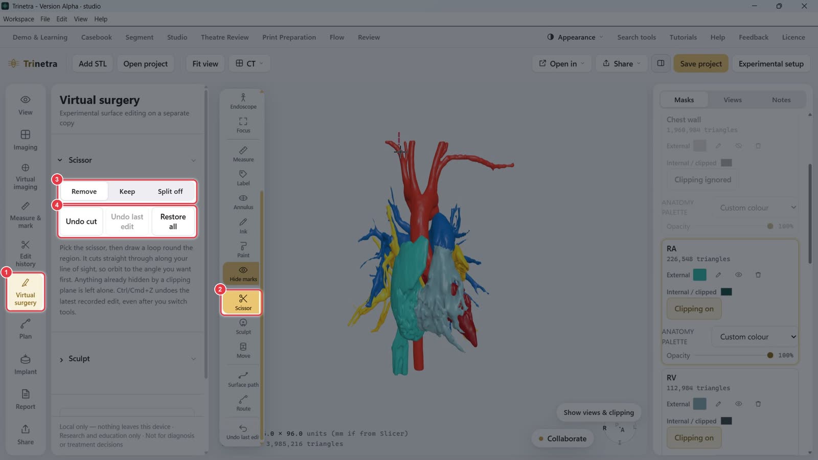
Click Virtual surgery in the left tool bar.
Or pick Scissor in the flyout.
Choose what the cut does: Remove the region, Keep only it, or Split off into a new mask.
Draw a loop around the region. The cut goes straight through along your line of sight, so rotate to the angle you want first. Undo cut or Restore all if needed.
Step 4Draw a surface path and build a patch
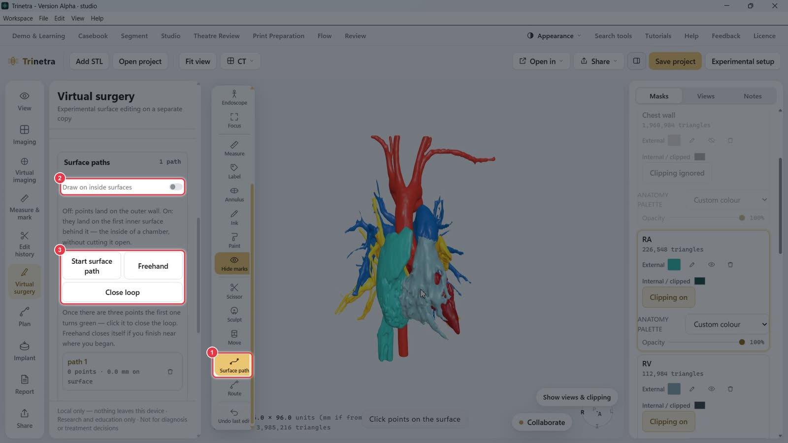
Pick Surface path in the flyout.
Draw on inside surfaces: off, points land on the outer wall. On, they land on the inner surface, inside a chamber.
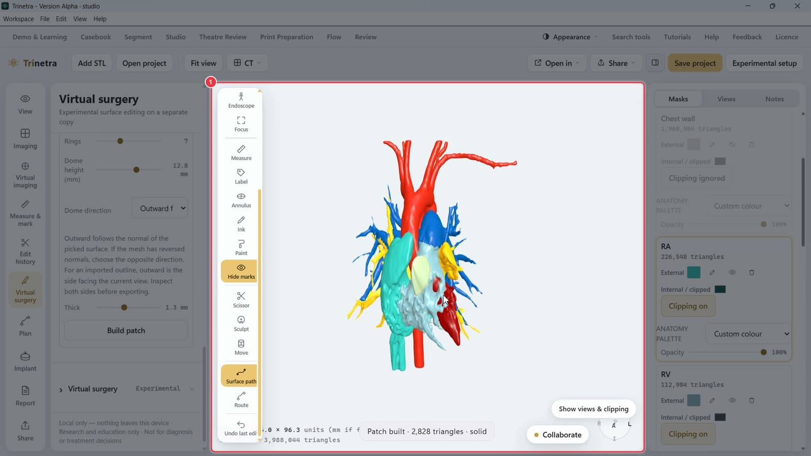
Click Start surface path (or Freehand) and click points on the surface. After three points the first turns green. Click it, or Close loop, to close the outline.
Under Patch from loop, set Rings, Dome height, Dome direction (outward/inward) and Thickness, then click Build patch. The patch appears as its own mask (e.g. patch 1).
Step 5Excise a wall on a virtual copy
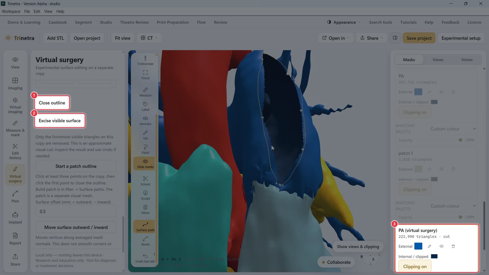
Under Virtual surgery, select a mask and click Copy selected mask for visual editing. The original is kept. Optionally Create wall shell to give the copy a wall thickness.
Click Start excision outline, click points around the area, then Close outline and Excise visible surface. Only the frontmost visible triangles are removed.
The edited copy appears as a new mask, e.g. PA (virtual surgery), marked cut.
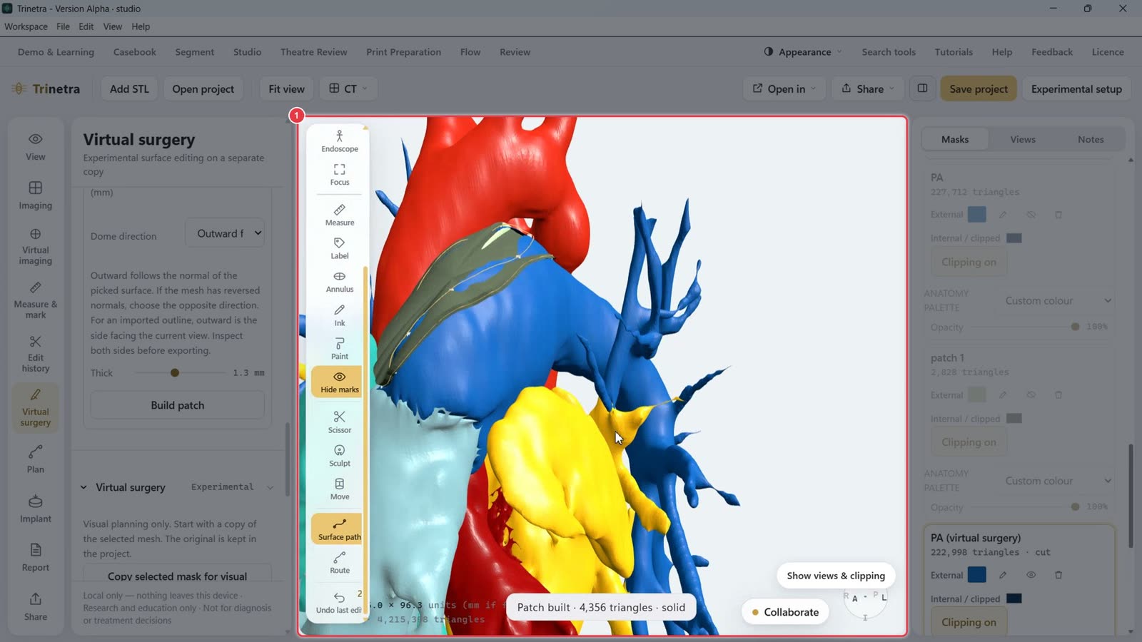
Draw a surface path around the opening and Build patch to close it. Here a patch is placed over the opened pulmonary artery.
Step 6Plan a conduit route
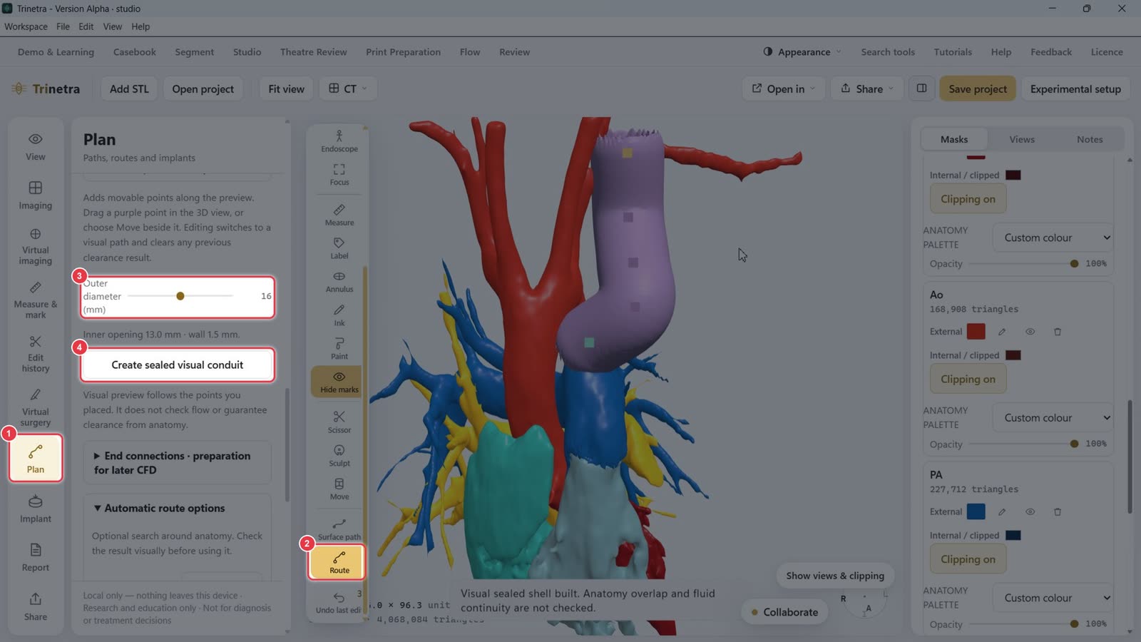
Click Plan in the left tool bar.
Or pick Route in the flyout. Click Start route, click a start point (e.g. on the aorta), then Add destination and click the end point (e.g. on the PA). Add guide points to shape the path. Preview path shows it, and you can drag the purple points to adjust.
Set the conduit's Outer diameter. The panel shows the inner opening and wall.
Click Create sealed visual conduit. The conduit is added as its own mask.
Step 7Generate an implant
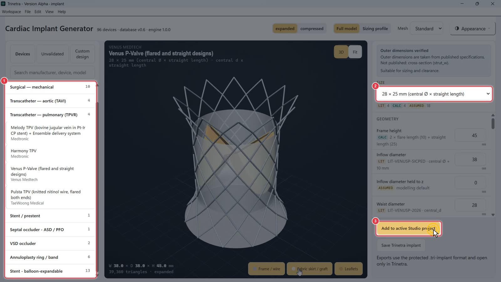
Click Implant, then Open implant generator. The Cardiac Implant Generator opens in its own window.
Browse device families (surgical valves, TAVI, TPVR, stents, occluders, rings) or search by manufacturer or model.
Pick a Size. Geometry is shown with its source: LIT (published), CALC (calculated) or ASSUMED.
Click Add to active Studio project. The device appears in Studio next to the model.
Step 8Fit annulus rings and align the implant
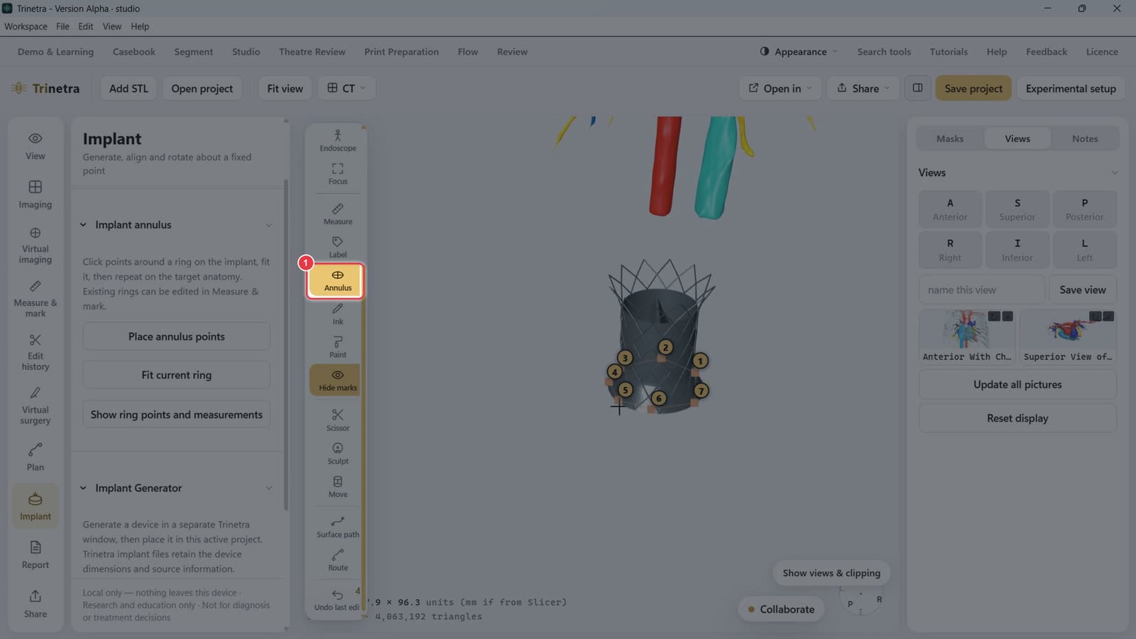
Pick Annulus in the flyout. Click Place annulus points and click points around the implant's rim (five is enough, more gives a better fit), then Fit current ring. Repeat on the target anatomy, e.g. the PA.
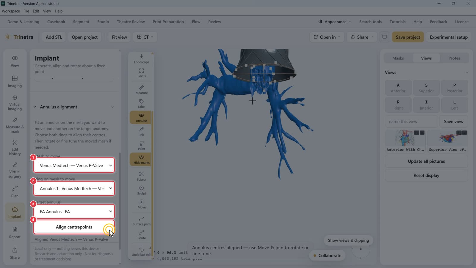
Under Annulus alignment:
Mesh to move: the implant.
Ring on mesh to move: the implant's annulus.
Target annulus: the anatomy's annulus (e.g. PA Annulus · PA).
Click Align centrepoints. The implant jumps to the target.
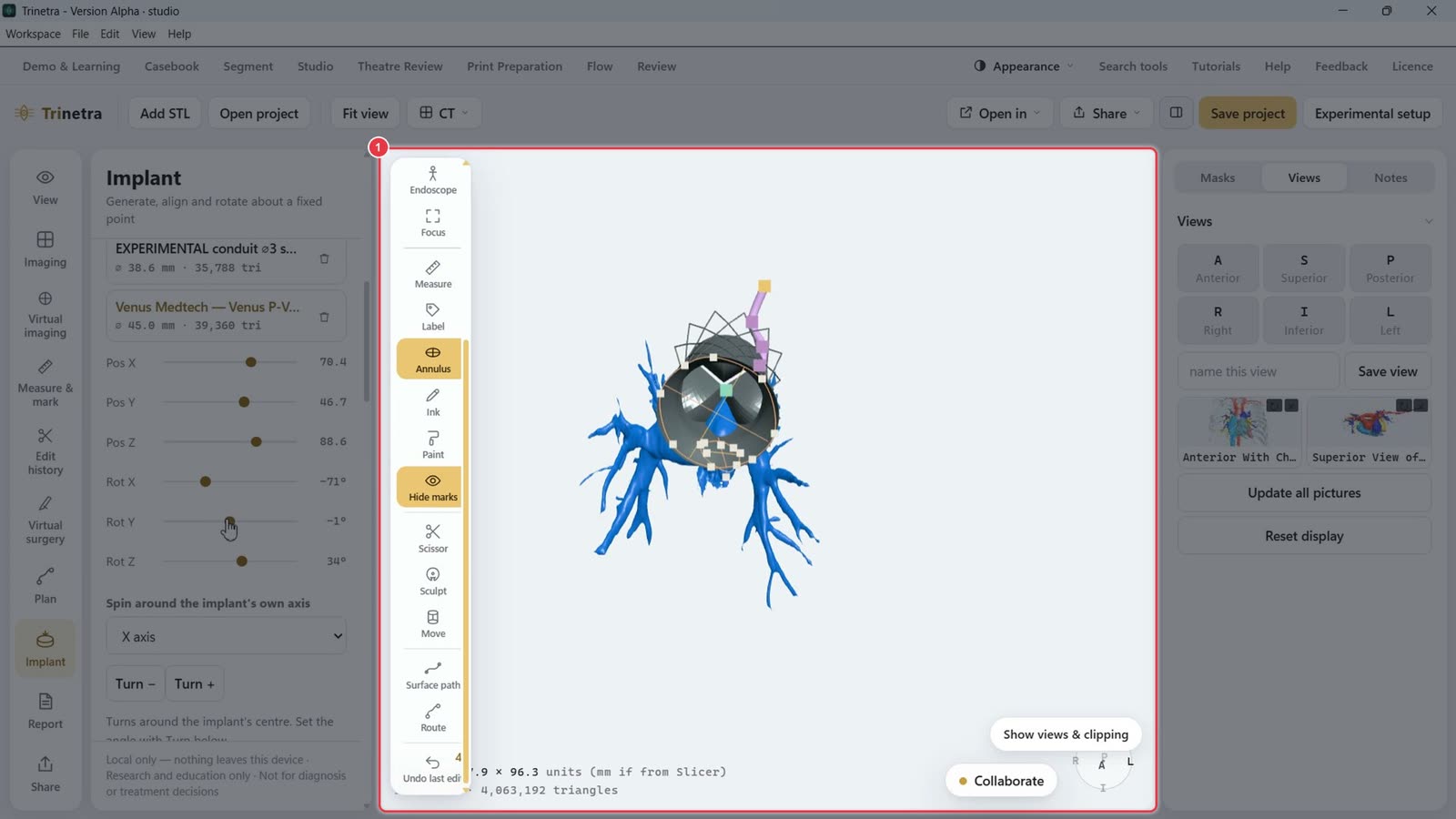
Fine-tune under Move & join: Pos X/Y/Z and Rot X/Y/Z sliders, or Spin around the implant's own axis with Turn −/+. Choose Fix an annulus point while turning to pivot around the ring.
Part 5 · Report · ~6 minutes
Reporting a case
Slow stretches such as typing are sped up. A red badge in the corner shows the speed.
The Report panel turns the case into a structured report: case details, captured figures, findings and plan, plus an optional sequential segmental analysis and the segmentation audit trail.
Step 1Open the Report panel and fill in the case details
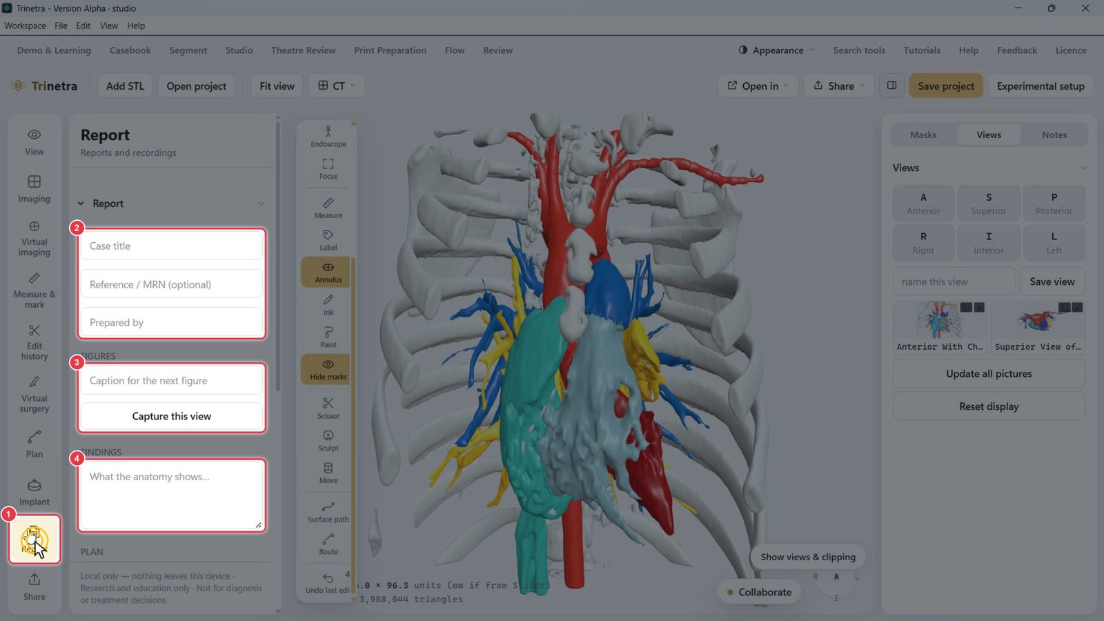
Click Report in the left tool bar.
Fill in Case title, Reference / MRN (optional) and Prepared by.
Under Figures, you'll caption and capture views (next step).
Findings and Plan come later.
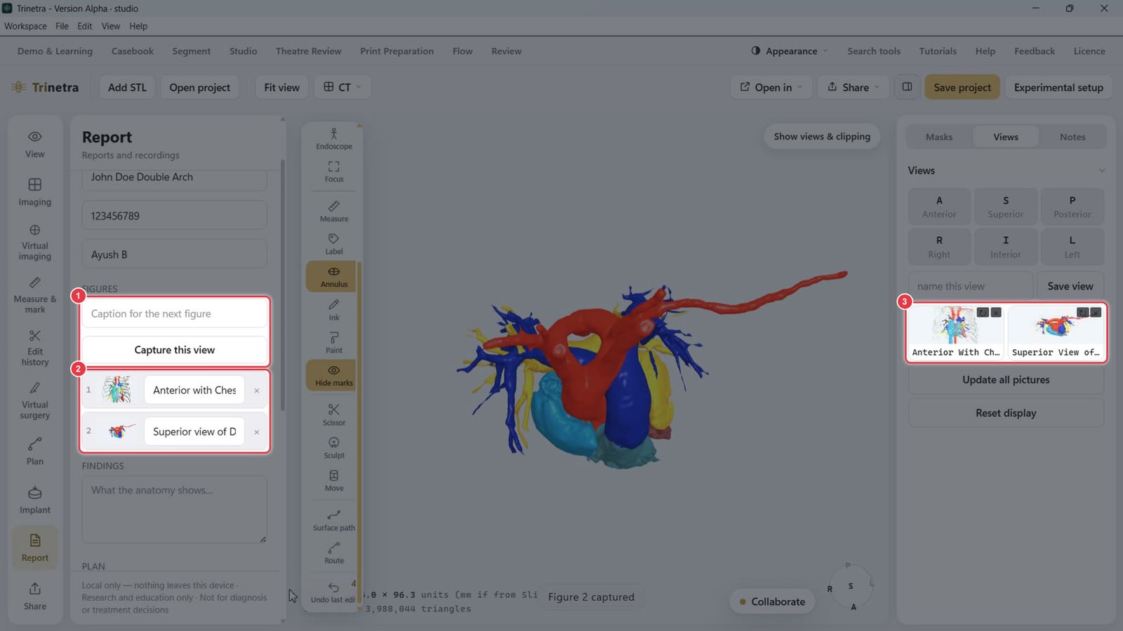
Step 2Capture figures
Set up the model as you want it in the report. Click a saved view on the Views tab to jump straight to it.
Type a caption in Caption for the next figure, then click Capture this view. Each figure is listed with its thumbnail and caption, and you can edit or remove it.
Your saved views from Part 3 are a quick way to get consistent angles.
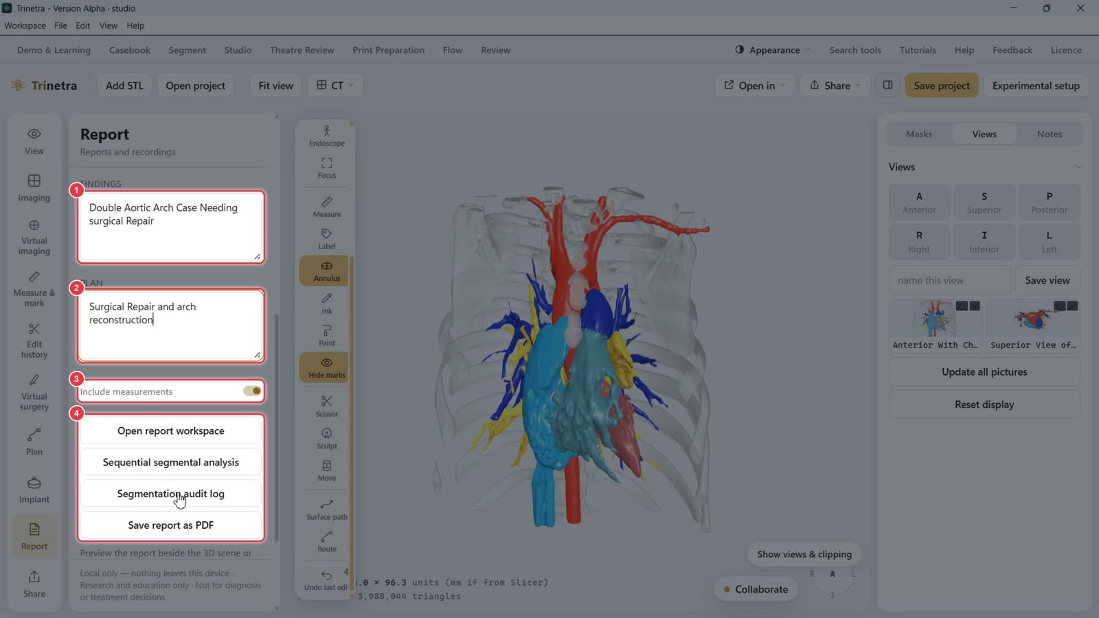
Step 3Write findings and plan
Findings: what the anatomy shows, e.g. "Double aortic arch case needing surgical repair".
Plan: the proposed approach, e.g. "Surgical repair and arch reconstruction".
Include measurements: adds measurements from Measure & mark to the report.
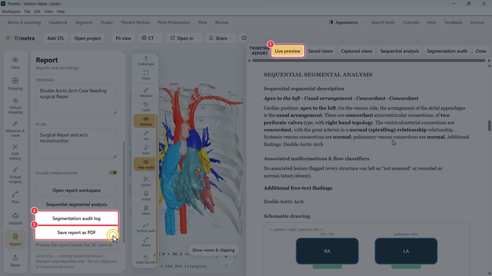
The report tools:
Open report workspace: preview the report beside the 3D scene.
Sequential segmental analysis: build a structured description (Steps 5–6).
Segmentation audit log: the record of every segmentation step.
Save report as PDF: export an A4 PDF.
Step 4Preview the report
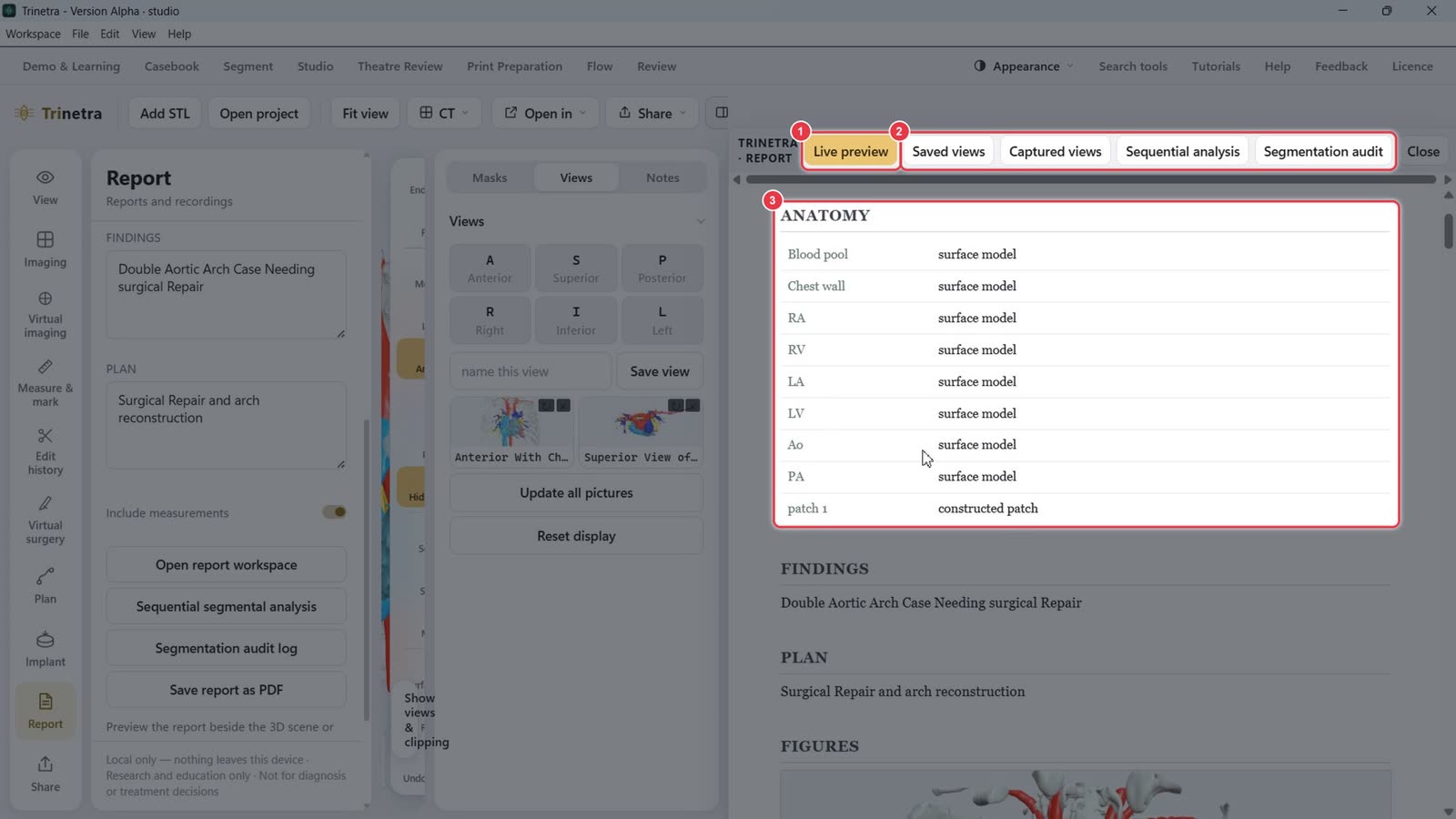
Click Open report workspace. The Live preview tab shows the report as it will print.
The other tabs: Saved views, Captured views, Sequential analysis and Segmentation audit.
The report lists every structure (anatomy), then Findings, Plan and Figures. It updates as you edit.
Step 5Sequential segmental analysis
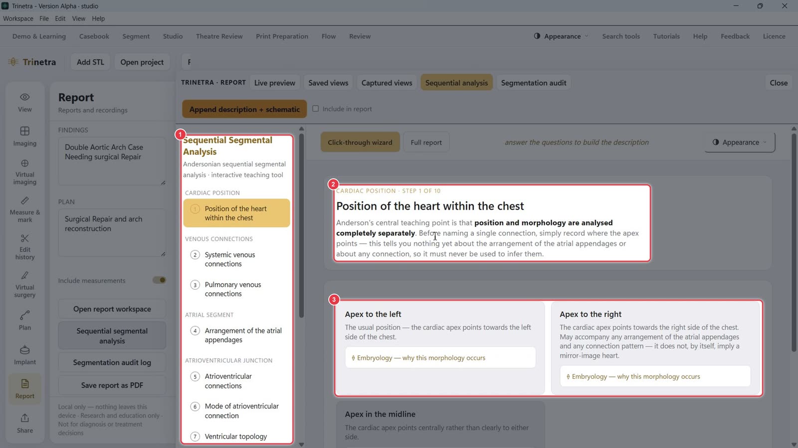
Click Sequential segmental analysis. It walks you through an Andersonian analysis one segment at a time.
The steps on the left: cardiac position, venous connections, atrial segment, AV junction, ventricles, arterial trunks. Completed steps get a tick.
Each step explains what to look at.
Click the card that matches the anatomy, e.g. Apex to the left. Open Embryology — why this morphology occurs to learn more.
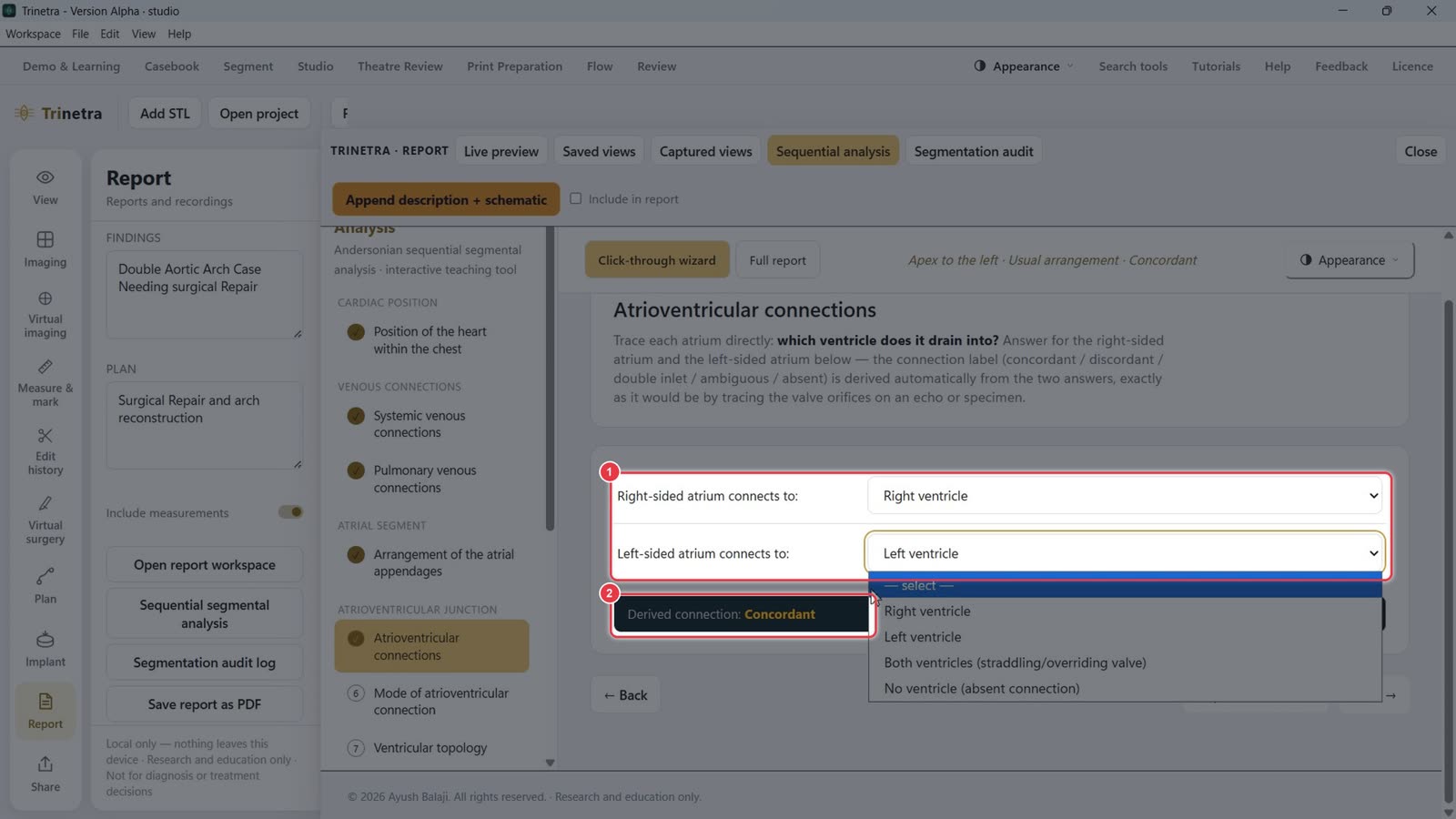
Some steps ask direct questions, e.g. which ventricle each atrium drains into.
Trinetra works out the connection label for you, e.g. Derived connection: Concordant. Use Next → to move on, or Skip — I don't know.
Step 6Add the analysis to the report
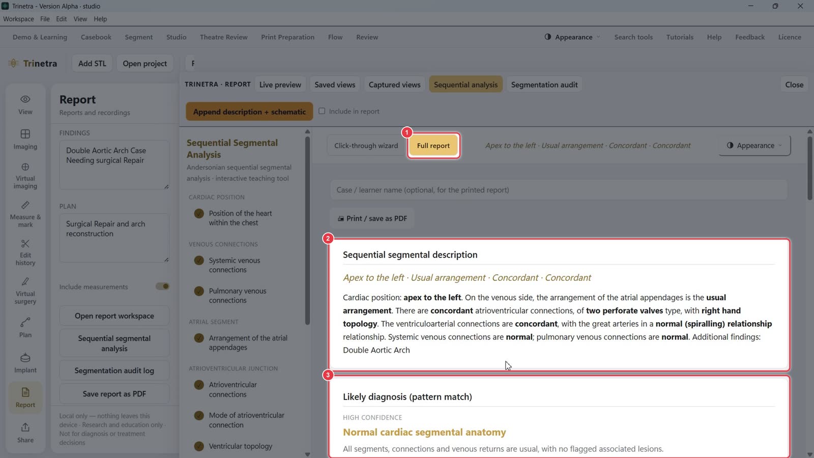
Click Full report to see the result.
The sequential segmental description is written out in full, e.g. Apex to the left · Usual arrangement · Concordant · Concordant.
Likely diagnosis (pattern match) suggests the best-fitting pattern with a confidence level.
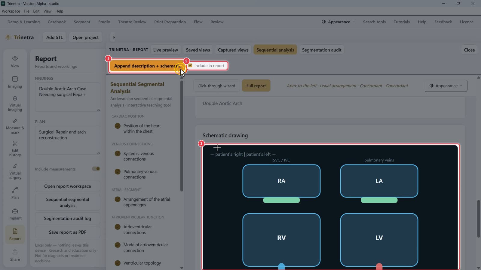
Tick Include in report and click Append description + schematic.
The checkbox confirms it's included.
A schematic drawing of the chambers and great arteries is generated and added to the report.
Step 7Check the audit trail and save
Back on Live preview, the report now includes the sequential analysis and the Segmentation activity audit: every segmentation step with its time. Patient identifiers are not logged.
Segmentation audit log opens the full log on its own.
Click Save report as PDF to export the finished report.
Trinetra runs locally. Nothing leaves this device. For research and education only, not for diagnosis or treatment decisions.